High-efficiency condensation-type flue gas waste heat recycling device

A flue gas waste heat and recovery device technology, which is applied in the direction of air heaters, fluid heaters, lighting and heating equipment, etc., can solve the problem of not fully utilizing the heat exchange efficiency of the water pipe group, limiting the recovery and utilization rate of flue gas waste heat, and the effective recovery of the recovery device. Space reduction and other issues, to achieve the effect of ensuring long-term maintenance-free use, improving air uniformity, and increasing recycling rates

Inactive Publication Date: 2016-08-03
ZHONGSHAN PRIMA IND
View PDF5 Cites 5 Cited by
  • Summary
  • Abstract
  • Description
  • Claims
  • Application Information

AI Technical Summary

Problems solved by technology

However, the above-mentioned waste heat recovery device has the following disadvantages: 1. The front fan of the recovery device occupies part of the space, which reduces the effective space of the recovery device and limits the utilization rate of waste heat recovery of flue gas; 2. The internal space of the recovery device is narrow, It affects the effect of air uniformity and cannot make full use of the heat exchange efficiency of the water pipe group; 3. The flow direction of the flue gas inside the recovery device is opposite to the direction of the condensate flow, and the condensate discharge speed is slow, easy to accumulate dust, and needs to be washed regularly; 4. Recovery The inlet of the front fan of the device is connected to the smoke collection chamber of the main heat exchanger on one side, which makes it difficult to evenly distribute the air in the main heat exchanger and also affects the heat exchange efficiency

Method used


Image

  • High-efficiency condensation-type flue gas waste heat recycling device
  • High-efficiency condensation-type flue gas waste heat recycling device
  • High-efficiency condensation-type flue gas waste heat recycling device

Examples


Embodiment Construction

[0025] The present invention will be further described below in conjunction with the accompanying drawings.

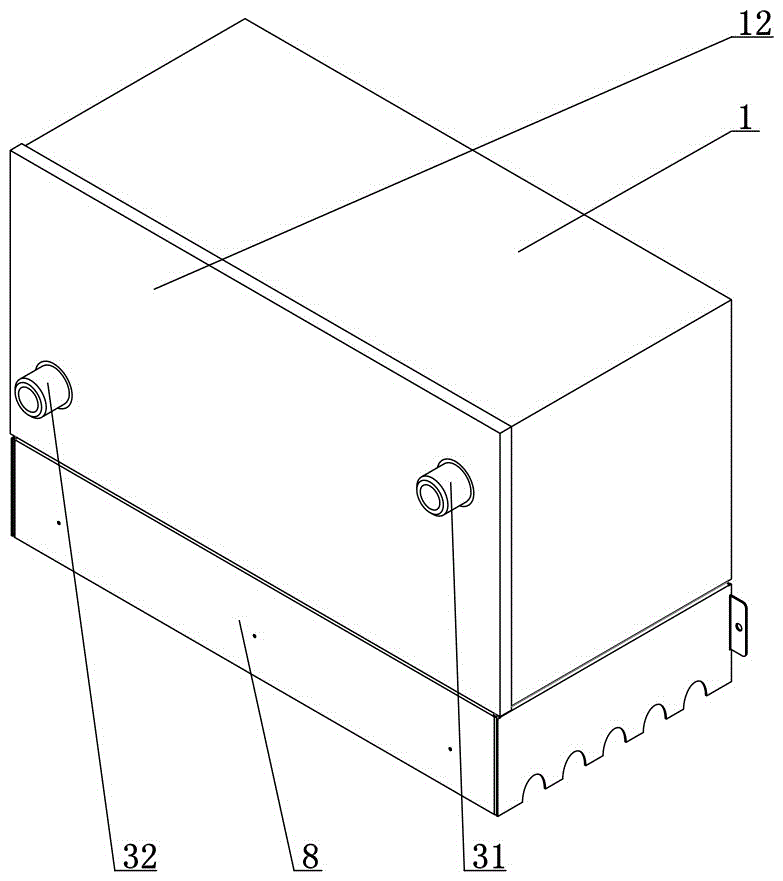
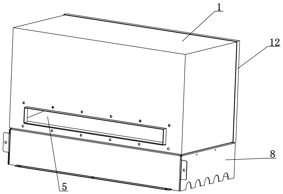
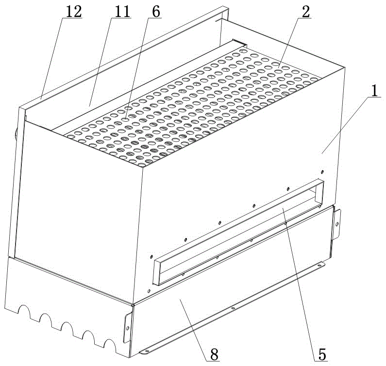
[0026] According to attached figure 1 to attach Figure 5 As shown, the high-efficiency condensing flue gas waste heat recovery device of the present invention includes the condensing box including the outer shell 1 with the condensing cavity 11, the condensing inner shell 2 with the condensing inner cavity 21, and the condensed water pipe with the function of equal resistance flow equalization Group 3. The condensing inner shell 2 is installed on the condensing chamber 11 , and the condensing water tube group 3 is installed on the condensing inner chamber 21 . The bottom of the condensing shell 1 is provided with a smoke inlet 4, the bottom of the condensing shell 1 is provided with a smoke collection chamber 8, and the cavity 81 of the smoke collection chamber communicates with the smoke inlet 4, that is, the collection chamber 4 at the bottom of the recovery devic...


PUM


Abstract

The invention provides a high-efficiency condensation-type flue gas waste heat recycling device. The device comprises a condensation outer shell, a condensation inner shell and a condensate pipe unit, wherein the condensation outer shell comprises a condensation chamber; the condensation inner shell comprises a condensation inner chamber; the condensate pipe unit comprises a water charging pipe and a water discharging pipe which are distributed diagonally; the condensation inner shell is mounted on the condensation chamber; the condensate pipe unit is mounted on the condensation inner chamber; a flue gas inlet is formed in the bottom surface of the condensation outer shell; a flue gas exhausting passage communicating with the condensation inner chamber is arranged on the bottom of the condensation outer shell; through holes communicating with the condensation chamber and the condensation inner chamber correspondingly are formed in the upper wall surface of the condensation inner shell; the flue gas inlet, the condensation chamber, the through holes, the condensation inner chamber and the flue gas exhausting passage form a flue gas waste heat recycling flow path which is used for heat exchange with the condensate pipe unit, so that the flowing resistance of the flue gas in the condensation inner chamber is equal, the condensate pipe unit is heated uniformly, sensible heat in high-temperature exhausted flue gas of a gas module and latent heat released by condensation of water steam can be fully absorbed, and thus returning water inside the condensate pipe unit can be effectively preheated, the flue gas heat energy recycle rate is increased, the thermal efficiency of the gas module is improved, and the using effect of the product is improved.

Description

technical field [0001] The invention relates to the field of gas boilers, in particular to a high-efficiency condensation type flue gas waste heat recovery device. Background technique [0002] Condensing gas modular furnace is a new type of central heating equipment, which has remarkable energy-saving and environmental protection effects. It is widely used in large-scale central heating and heating in factories, office buildings, commercial and residential areas, hospitals, supermarkets, hotels, bath centers, swimming pools, etc. water. [0003] Several gas modules are installed inside the furnace body of the above-mentioned gas modular furnace, and the gas modules communicate with the smoke outlet above the furnace body through the smoke collecting pipe. When the gas-fired modular furnace is working, the fuel burns to generate high-temperature heat energy, and after passing through the main heat exchanger, high-temperature flue gas at 160 ° C to 200 ° C will be discharg...

Claims


Application Information

Patent Timeline
Patent Type & Authority Applications(China)
IPC IPC(8): F24H9/00F24H8/00
CPCF24H8/00F24H9/0005F24H9/0036Y02B30/00
Inventor 刘永义
Owner ZHONGSHAN PRIMA IND
Why Eureka
Try Eureka