
An uncooled optical athermalized lens

An uncooled, optical technology, applied in the optical field, can solve the problems affecting the imaging quality of the infrared imaging system, and achieve the effect of high transmittance, simple system structure, and clear imaging.

Active Publication Date: 2018-06-26
11TH RES INST OF CHINA ELECTRONICS TECH GROUP CORP
View PDF5 Cites 0 Cited by
  • Summary
  • Abstract
  • Description
  • Claims
  • Application Information

AI Technical Summary

Problems solved by technology

[0003] In view of the above analysis, the present invention aims to provide a compact uncooled optical athermalization lens to solve the problem that temperature affects the imaging quality of infrared imaging systems in the prior art

Method used


Image

  • An uncooled optical athermalized lens
  • An uncooled optical athermalized lens
  • An uncooled optical athermalized lens

Examples


Embodiment Construction

[0029] Preferred embodiments of the present invention will be specifically described below in conjunction with the accompanying drawings, wherein the accompanying drawings constitute a part of the application and are used together with the embodiments of the present invention to explain the principles of the present invention. For the sake of clarity and simplicity, detailed descriptions of known functions and constructions in the devices described herein will be omitted when it may obscure the subject matter of the present invention.

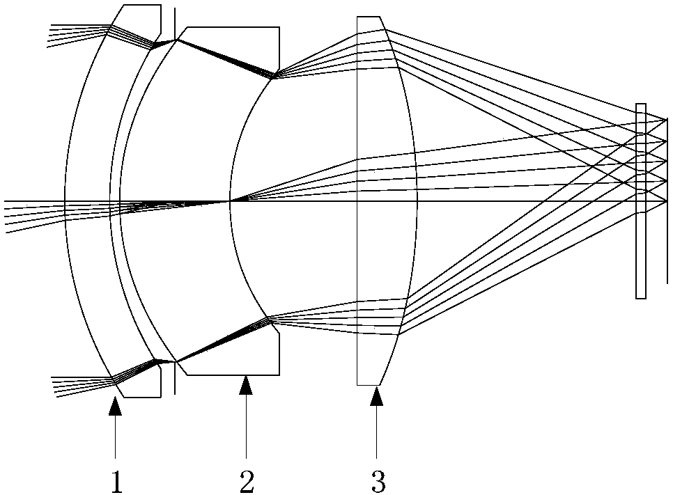
[0030] In order to solve the problem that the temperature affects the imaging quality of the infrared imaging system in the prior art, the present invention provides a compact uncooled optical athermalization lens, in which a negative meniscus lens, a positive meniscus lens and a positive lens are sequentially arranged along the light incident direction , by adjusting the F number and the focal length of each lens to achieve clear imaging in the...


PUM


Abstract

The invention discloses a non-refrigeration optical athermalization lens, a negative crescent lens, a positive crescent lens and a positive lens are arranged in sequence along a light incidence direction, and an effect that an object can be clearly imaged in a range of -40 degrees to +60 degrees without focusing is achieved through adjustment of an F number and the focal length of each lens.

Description

technical field [0001] The invention relates to the field of optical technology, in particular to an uncooled optical athermalized lens. Background technique [0002] In recent years, with the continuous development of uncooled detector technology, the sensitivity of uncooled detectors has been continuously improved, and the cost has been continuously reduced, making infrared imaging systems widely used in night vision, vehicle night vision and security monitoring. more and more widely. However, one disadvantage of infrared imaging systems is that it is difficult to adapt to a wide operating temperature range. Since the temperature coefficient of refractive index of infrared materials varies greatly, as the ambient temperature changes, the refractive index of infrared optical materials, the curvature, thickness and spacing of components will change, and the thermal expansion and contraction of the shell will make the system Defocus and other aberrations will seriously affe...

Claims


Application Information

Patent Timeline
Patent Type & Authority Patents(China)
IPC IPC(8): G02B13/00G02B13/18
CPCG02B13/0035G02B13/18
Inventor 杨加强刘琳彭晴晴孙昌锋
Owner 11TH RES INST OF CHINA ELECTRONICS TECH GROUP CORP
Learn More