Time delay circuit and voltage-controlled oscillator

A delay circuit, power supply voltage technology, applied in the direction of electrical components, automatic power control, etc., to achieve the effects of low phase noise, enhanced equivalent impedance, and enhanced gain

Active Publication Date: 2016-08-03
SEMICON MFG INT (SHANGHAI) CORP
View PDF5 Cites 3 Cited by
  • Summary
  • Abstract
  • Description
  • Claims
  • Application Information

AI Technical Summary

Problems solved by technology

[0004] The problem solved by the embodiment of the present invention is how to reduce the phase noise of the delay circuit

Method used


Image

  • Time delay circuit and voltage-controlled oscillator
  • Time delay circuit and voltage-controlled oscillator
  • Time delay circuit and voltage-controlled oscillator

Examples


Embodiment Construction

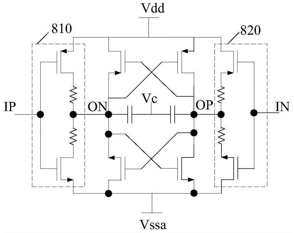
[0021] figure 1 Shown is a delay circuit structure. It adjusts the RC constants of the output nodes ON and OP through voltage-controlled variable capacitors to achieve variable delay, and reduces the delay circuit through resistive components connected to the drains of inverter 810 and inverter 820 Sensitivity to temperature and supply voltage. However, the introduction of this resistive component leads to a deterioration of the phase noise of the oscillator. In the delay circuit, the adjustment unit that converts the input control voltage into a current is difficult to achieve a small phase noise when covering the required frequency range.

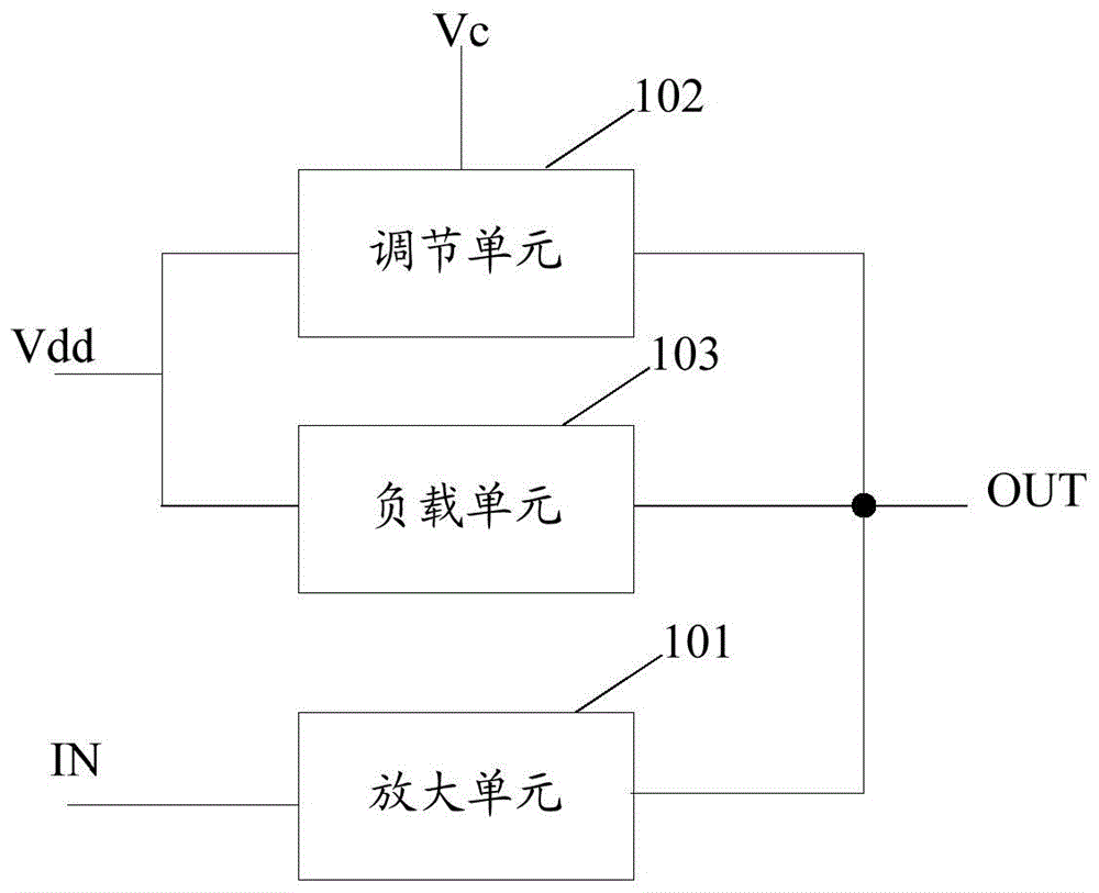
[0022] figure 2 A schematic structural diagram of a delay circuit in an embodiment of the present invention is shown. like figure 2 As shown, the delay circuit may include: an amplification unit 101 , an adjustment unit 102 and a load unit 103 . The amplification unit 101 is coupled to the input terminal IN and the output terminal...


PUM


Abstract

The invention relates to a time delay circuit and a voltage-controlled oscillator. The time delay circuit comprises an amplifying unit, a regulating unit and a load unit, wherein the amplifying unit is coupled to an input end and an output end of the time delay circuit, the regulating unit is coupled to the output end of the time delay circuit, power supply voltage and control voltage respectively, and the load unit is coupled to the output end of the time delay circuit and the power supply voltage; the regulating unit is suitable for regulating charging and discharging current of the time delay circuit; the amplifying unit is suitable for amplifying output voltage of the time delay circuit; and the load unit is suitable for providing negative impedance for the regulating unit. Through the time delay circuit and the voltage-controlled oscillator, phase noises of the time delay circuit can be reduced, and low voltage gain is realized.

Description

technical field [0001] The invention relates to the technical field of electronic circuits, in particular to a delay circuit and a voltage-controlled oscillator. Background technique [0002] Phase-locked loop (Phase-Locked Loop, PLL) is the core circuit in various communication and clock chips, and the spectral noise, jitter, spurious and other indicators of its output signal will directly affect the system performance. The voltage controlled oscillator is an important part in the PLL. When the control voltage changes within a certain range, a signal output within a continuous frequency range can be obtained. The ring oscillator is one of the main implementation methods, which generates an oscillating voltage signal by connecting the delay circuits end to end to form a feedback loop. Ring oscillators include both single-ended and differential circuit structures. [0003] In the delay circuit of the existing ring oscillator design, the adjustment unit part that converts t...

Claims


Application Information

Patent Timeline
Patent Type & Authority Applications(China)
IPC IPC(8): H03L7/099H03L7/08
Inventor 贾海珑陈先敏
Owner SEMICON MFG INT (SHANGHAI) CORP
Why Eureka
Try Eureka