Position indicating module and stylus pen

A technology of stylus and electrodes, which is applied in the direction of user/computer interaction input/output, instrument, calculation, etc., which can solve the problems such as difficult pen refill replacement and achieve the effect of easy replacement

Active Publication Date: 2016-08-03
WACOM CO LTD
View PDF12 Cites 18 Cited by
  • Summary
  • Abstract
  • Description
  • Claims
  • Application Information

AI Technical Summary

Problems solved by technology

In addition, there are problems such as that it is not e

Method used


Image

  • Position indicating module and stylus pen
  • Position indicating module and stylus pen
  • Position indicating module and stylus pen

Examples


no. 1 Embodiment approach

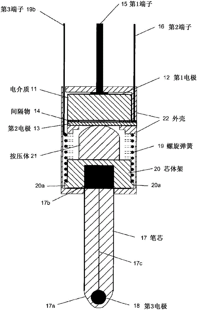
[0055] figure 1 It is a figure which shows the structure diagram (central cross-sectional view) of an example of the position indication module of 1st Embodiment of this invention. exist figure 1 Among them, 11 denotes a substantially disk-shaped dielectric, 12 denotes a first electrode provided on the first surface of the dielectric 11, and 13 denotes a second electrode made of a flexible material. The second electrode 13 is disposed on the second surface side of the dielectric 11 opposite to the first surface with the ring-shaped spacer 14 interposed therebetween. For the second electrode 13 , for example, conductive rubber can be used, or a material obtained by vapor-depositing a conductive substance on one surface of polyimide can be used.

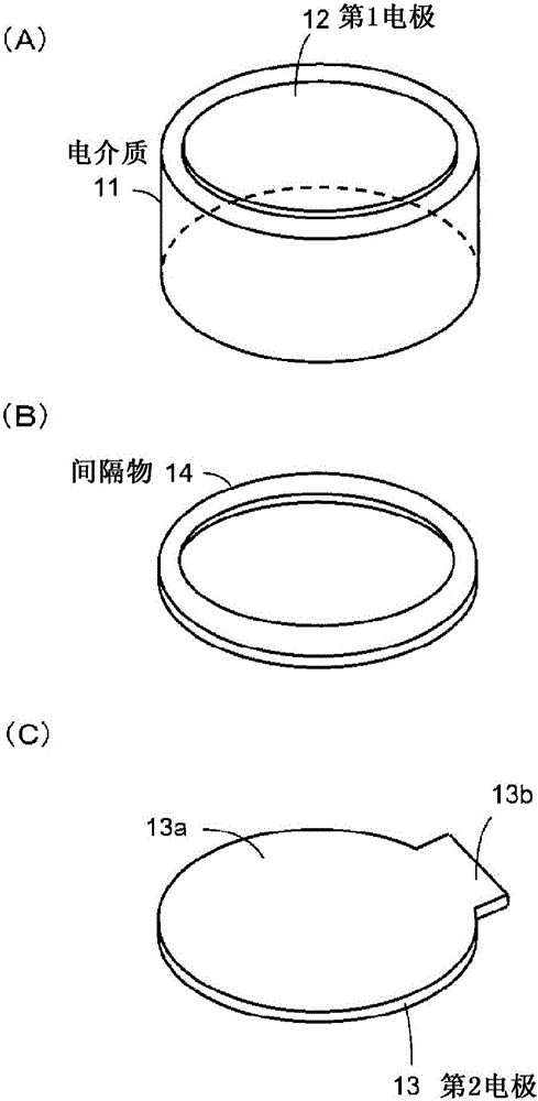
[0056] figure 2 It is a perspective view when the dielectric 11, the spacer 14, and the second electrode 13 are respectively arranged in disassemble. At least the surface 13 a side of the second electrode 13 in contact with the sp...

no. 2 Embodiment approach

[0069] [Second Embodiment (Modification of First Embodiment)]

[0070] Figure 5 It is a figure which shows the structure diagram (central sectional view) of an example of the position indication module of 2nd Embodiment, and figure 1 Parts having the same configuration as the position indicating modules of the first embodiment shown are denoted by the same reference numerals. The second embodiment has a lot in common with the first embodiment, so here only figure 1 The different sections are explained.

[0071] 23 represents a coil spring formed of a conductive material, which is basically the same as that used in the first embodiment Figure 4 The coil spring 19 shown is the same, but does not have a portion corresponding to the straightly extending portion, ie, the terminal 19b. The coil spring 23 is inserted into the core frame 20 similarly to the coil spring 19 of the first embodiment, and is in contact with the protruding portion 20 a to be electrically connected.

...

no. 3 Embodiment approach

[0078] Figure 7 is a diagram showing a structural view (central sectional view) of an example of the position indication module of the third embodiment, and figure 1 Parts having the same configuration as the position indicating modules of the first embodiment shown are denoted by the same reference numerals.

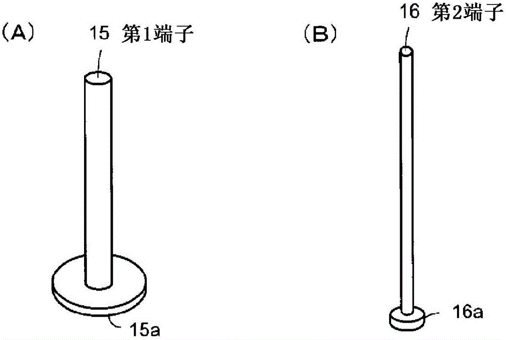
[0079] That is, 11 denotes a substantially disk-shaped dielectric, 12 denotes a first electrode provided on the first surface of the dielectric 11, and 14 denotes a spacer. 15 denotes a first terminal formed of metal, which is electrically connected to the first electrode 12 of the dielectric 11 . 16 denotes a second terminal formed of metal. 17 denotes a substantially rod-shaped refill, and a third electrode 18 is embedded in the front end 17a. A conductive substance is applied to the connection end 17 b of the lead 17 , and the connection end 17 b is electrically connected to the third electrode 18 via a conductor 17 c provided inside the lead 17 . The configurat...


PUM


Abstract

Provided is a position indicating module for an electrostatic stylus pen, said module having an easily exchangeable core body and being able to accurately detect changes in pen pressure caused by light touch. The position indicating module for an electrostatic stylus pen transmits a signal from an electrode included in the core body, and contains: a dielectric body including a first surface and a second surface that faces the first surface; a first electrode disposed on the first surface of the dielectric body; a second electrode positioned to face the second surface and having a contact surface area with the second surface that changes due to an external force; and a core-body part that includes a third electrode at at least the tip and conveys the external force to the second electrode. The position indicating module also contains are a first terminal that electrically connects to the first electrode, a second terminal that electrically connects to the second electrode, and a third terminal that electrically connects to the third electrode. The position indicating module further contains a fitting part which is for electrically connecting the third electrode and the third terminal by contacting the core-body part to the third terminal while being biased.

Description

technical field [0001] The present invention relates to a position indication module and a stylus used for inputting an indication position on a tablet. Background technique [0002] Prior to this application, the applicant has proposed in Patent Document 1 (Japanese Patent Laid-Open No. 2007-164356 ) a position indicator that provides a coil and electrodes in a position indicating portion to obtain a coordinate position on a flat panel. According to this position indicator, by installing a variable capacitance capacitor whose capacitance changes according to the pen pressure, the pen pressure is converted into a digital value and transmitted, so that the pen pressure can be detected with high precision, and a position indicator with excellent operability can be realized. [0003] Regarding variable capacitance capacitors whose capacitance changes according to pen pressure, variable capacitors using dielectrics are disclosed in Patent Document 2 (Japanese Patent Laid-Open No...

Claims


Application Information

Patent Timeline
IPC IPC(8): G06F3/03G06F3/0354
CPCG06F3/03545G06F3/0383
Inventor 桂平勇次
Owner WACOM CO LTD
Why Eureka
Try Eureka