Electric machine having in each case at least two clamping protrusions for attaching a permanent magnet

A permanent magnet and clamping technology, which is applied in the direction of magnetic circuits, electrical components, electromechanical devices, etc., can solve the problems of difficult installation of permanent magnets, and achieve the effects of small torque fluctuation, small positioning torque, and low cost

Active Publication Date: 2016-08-03
ROBERT BOSCH GMBH
View PDF3 Cites 6 Cited by
  • Summary
  • Abstract
  • Description
  • Claims
  • Application Information

AI Technical Summary

Problems solved by technology

However, it has been found that the mounting of the perman

Method used


Image

  • Electric machine having in each case at least two clamping protrusions for attaching a permanent magnet
  • Electric machine having in each case at least two clamping protrusions for attaching a permanent magnet
  • Electric machine having in each case at least two clamping protrusions for attaching a permanent magnet

Examples


Example Embodiment

[0052] FIG. 2 shows a first embodiment of a spoked rotor 10 for such an electric machine 100 .

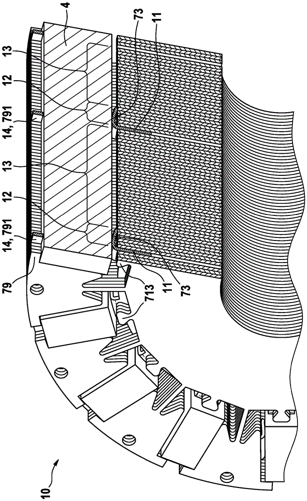
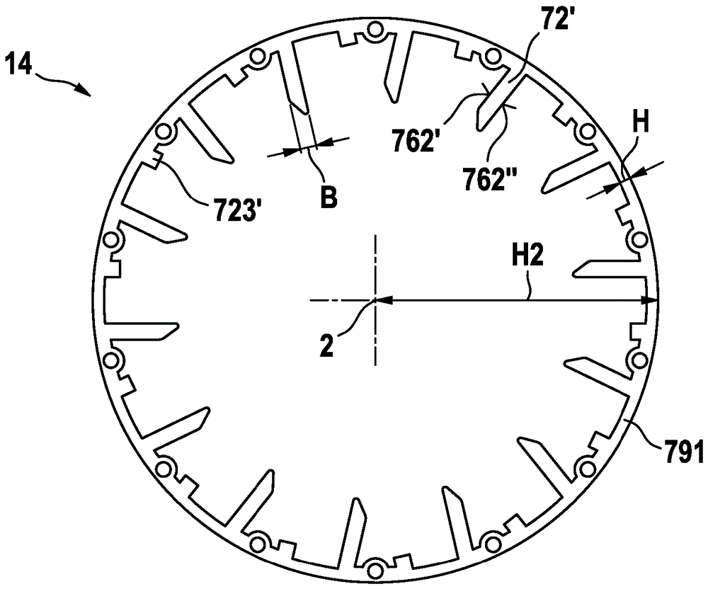
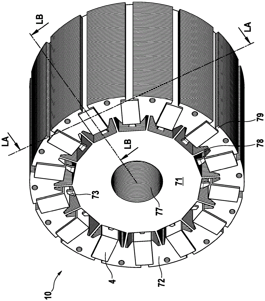
[0053] The spoked rotor 10 has a base body 1 which is produced as a lamellar pack of a plurality of laminae 11 , 12 , 13 . Figure 2(a) shows the clamping foil 11 of the spoked rotor 10, Figure 2(b) shows the balancing foil 12 of the spoked rotor 10, and Figure 2(c) shows the Middle lamination 13 of spoked rotor 10 . The finished substrate 1 is shown in FIG. 2( d ). And Figures 2(e)-(g) respectively show a spoked rotor 10 with permanent magnets 4 arranged in the base body (1).

[0054] The lamellae 11 , 12 , 13 are preferably produced in one piece as punched-out parts from web material. For the clamping laminations 11 , either the steels conventionally used for laminations of such rotors 10 , preferably ferrous, or spring steels can be used. For the remaining sheets 12, 13 conventional steel is used.

[0055] The clamping lamination 11 has an inner ring 71 which in turn has a p...


PUM


Abstract

The invention discloses an electric machine having in each case at least two clamping protrusions for attaching a permanent magnet. The present invention relates to a spoke rotor for an electric machine, having a main body which extends concentrically around an axis of rotation and which has a plurality of pole shoes, between which permanent magnets are arranged in holders, wherein there is provided for each permanent magnet in its holder in each case at least one first clamping element and one second clamping element, which fixes said permanent magnet in the holder, wherein the first clamping element fixes the permanent magnet in a radial direction relative to the axis of rotation and the second clamping element fixes it in a tangential direction relative to the axis of rotation, and wherein in each case a movement clearance is provided for each second clamping element. The present invention also relates to a clamping lamella, in particular for such a spoke rotor. The present invention also relates to an electric machine comprising such a spoke rotor. The present invention also relates to a device, in particular a hand-held power tool, an adjustment drive for a motor vehicle, a power steering system, a servo motor, an electromechanical brake booster or a vehicle drive, comprising such an electric machine.

Description

technical field [0001] The invention relates to the positioning and fixing of permanent magnets in a spoked rotor of a brushless permanent magnet-excited electric machine. Background technique [0002] Electric machines with a brushless inner rotor designed as a spoked rotor are used in numerous applications. An example is an electric power steering machine (EPS, E lectric P ower-assisted S teeringdrive), drives for cooling circuits of combustion motors, vehicle drives for electric scooters or bicycles (eScooter, eBike), electromechanical brake amplifiers (iBooster), active stabilization in motor vehicles tor (ARS, A active R oll S tabilisation), for industrial automation devices, for robots and servo motors for machine tools. Rectangular permanent magnets are arranged in such a rotor like the spokes of a bicycle. The permanent magnets thus extend along their length towards the axial direction of the rotor, along their width towards the radial direction and along the...

Claims


Application Information

Patent Timeline
IPC IPC(8): H02K1/27
CPCH02K1/2773
Inventor S.埃文斯S.A.埃文斯T.克尼希
Owner ROBERT BOSCH GMBH
Why Eureka
Try Eureka