Chain belt type plate pulling machine

A chain belt type, trigger technology, applied in the field of plate processing, can solve the problems of discontinuous force, damage deformation, unevenness of the plate, etc., to achieve the effect of saving work space, continuous tension, and wide application range

Inactive Publication Date: 2016-08-10
邹城市兴企新型建材有限公司
View PDF0 Cites 0 Cited by
  • Summary
  • Abstract
  • Description
  • Claims
  • Application Information

AI Technical Summary

Problems solved by technology

[0003] In order to solve the problems of the large working space of the plate pulling machine and the discontinuous and uneven force on the plate causing damage and deformation, the invention provides a chain-belt type plate pulling machine

Method used


Image

  • Chain belt type plate pulling machine
  • Chain belt type plate pulling machine
  • Chain belt type plate pulling machine

Examples


Embodiment Construction

[0023] Embodiments of the present invention will be further described below in conjunction with the accompanying drawings.

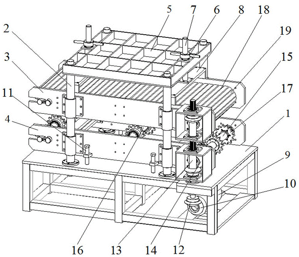
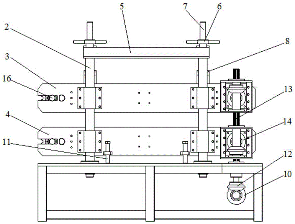
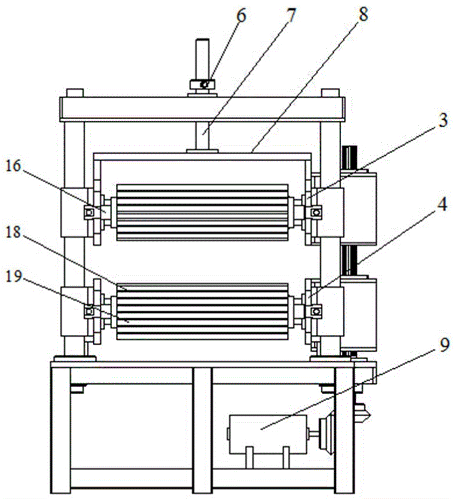
[0024] Such as figure 1 As shown, a chain belt type drawing machine includes a machine base 1, 4 guide rods 2, an upper pressure roller frame 3, a lower pressure roller frame 4, an upper bracket 5, 2 handles 6, 2 screw rods 7, 2 lifting frames 8, motor 9, motor helical gear 10, 4 positioning screws 11, 3 transmission rod helical gears 12, transmission rod 13, 2 power shaft helical gears 14, 2 power shafts 15, 4 rotating shafts 16 , 18 chain pulleys 17, 2 chain belts 18, several rubber pressing blocks 19.

[0025] The lower ends of the four guide rods 2 are vertically fixed on the machine base 1, the upper ends are fixedly connected with the upper bracket 5, and the middle ends are movably connected with the lower roller frame 4 and the upper roller frame 3 from bottom to top.

[0026] The lower pressure roller frame 4 is positioned on the machine base ...


PUM


Abstract

A chain-belt type drawing machine, belonging to the field of plate processing, including a machine base; 4 guide rods are fixed on the machine base, connected with the lower pressure roller frame, the upper pressure roller frame, and the upper bracket from bottom to top; the lower pressure roller The frame includes a power shaft, 2 rotating shafts, a chain belt, and 9 chain pulleys; 3 chain pulleys are arranged on the power shaft and 2 rotating shafts, and the chain belt surrounds the outside of the chain pulley, and a pressure block is set on the chain belt; The structure of the pressure roller frame and the lower pressure roller frame is arranged in a one-to-one correspondence, and the motor transmission rod provides power to the power shaft through the meshing of the helical gear; the plate is placed within the distance between the upper and lower pressure roller frames, Stretching, continuous drawing, continuous and uniform pulling force, will not cause damage to the sheet; at the same time, the machine base is fixed to save working space.

Description

technical field [0001] The invention belongs to the field of plate processing, in particular to a chain belt type plate pulling machine. Background technique [0002] At present, the plate pulling machine used in the field of plate processing usually clamps the plate through the splint, the entire plate pulling machine moves backwards, stops at a certain position, and then the splint is released, and the plate pulling machine returns to the original position forward and then clamps , so that the reciprocating action realizes the pulling plate. The above-mentioned plate pulling machine has a large forward and backward movement distance, requiring a large working space, and due to the reciprocating tension of the splint when pulling the plate, the force on the produced plate is discontinuous and uneven, and the plate is greatly damaged and deformed, which seriously affects the quality of the plate. Contents of the invention [0003] In order to solve the problems of large w...

Claims


Application Information

Patent Timeline
Patent Type & Authority Applications(China)
IPC IPC(8): B21C1/16
CPCB21C1/16
Inventor 李先刚
Owner 邹城市兴企新型建材有限公司
Why Eureka
Try Eureka