Automotive suspension swing arm structure

A technology of automobile suspension and main body, which is applied to the suspension, the cantilever mounted on the pivot, and vehicle parts, etc., which can solve the problems of lower bearing capacity of the swing arm, stress concentration, and lifting the swing arm, so as to improve the stiffness of the swing arm and fatigue strength, to meet the effect of light weight and reasonable force

Inactive Publication Date: 2016-08-10
CHONGQING CHANGAN AUTOMOBILE CO LTD
View PDF5 Cites 6 Cited by
  • Summary
  • Abstract
  • Description
  • Claims
  • Application Information

AI Technical Summary

Problems solved by technology

[0004] However, according to the CAE fatigue simulation analysis and swing arm bench test of this form of swing arm structure, it will be found that the upper body of the swing arm is prone to stress in the area near the large rubber bushing and metal sleeve under the premise that the stiffness and fatigue performance of the lower body of the swing arm are sufficiently high Concentration phenomenon reduces the bearing capacity of the swing arm, cracks appear in the swing arm, and there is a risk of failure
[0005] Because the suspension swing arm needs to bear sufficient load strength, it cannot be cracked and failed to affect safety. At the same time, it is limited by the cost, manufacturing process and vehicle weight, and it is impossible to increase the material thickness of the swing arm body and improve the material strength. Brand or adopt new technology to improve the stiffness and fatigue performance of the swing arm to solve the cracking problem of the swing arm

Method used


Image

  • Automotive suspension swing arm structure
  • Automotive suspension swing arm structure
  • Automotive suspension swing arm structure

Examples


Embodiment Construction

[0020] The present invention will be further described in detail below in conjunction with the accompanying drawings and examples. The following examples are only used to explain the present invention, and do not constitute a limitation to the protection scope of the present invention.

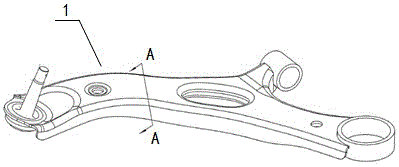
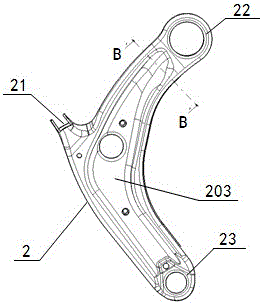
[0021] Such as Figure 3 to Figure 6 The automobile suspension swing arm structure shown includes a swing arm main body 2 and a reinforcing plate 3 . The edge of the main body of the swing arm 2 has an edge 201, and the three corners of the main body of the swing arm are respectively provided with a shaft bush installation hole 21, a large bush installation hole 22 and a ball pin installation hole 23. The hole 21 is used to connect the metal sleeve of the shaft bushing, the large bush installation hole 22 is used to connect the metal sleeve of the large rubber bush, and the ball pin installation hole 23 is used to connect the ball pin.

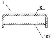
[0022] There is a section of flanging body 202 turned i...


PUM


Abstract

The invention discloses an automotive suspension swing arm structure. The structure comprises a swing arm body and a reinforcing plate, wherein edges are arranged on the edge of the swing arm body, a section of inwards folded turned edge body is arranged in a position, near a large bushing mounting hole, of the edge on the same side with a shaft bushing mounting hole, the center of the swing arm body dents downwards to form a groove, the section, near the large bushing mounting hole, of the groove is an asymmetric groove, the groove bottom surface adopts smooth transition of multiple sections of cambered surfaces with different curvature radiuses, and the lowest point of the groove bottom surface is relatively close to the turned edge body. On the premise that the thickness of the swing arm body is not increased, the material trademark is not improved and the existing manufacturing technology is not changed, the swing arm structure reasonable in stress and simple in structure is proposed according to the mechanical environment and the structure characteristic of the suspension swing arm, the rigidity and fatigue performance of the swing arm structure are substantially improved, and the problem of crack failure can be avoided.

Description

technical field [0001] The invention relates to an automobile suspension system, in particular to an automobile suspension swing arm structure. Background technique [0002] The suspension swing arm is used to connect the suspension steering knuckle and the suspension subframe, and is a key component of the vehicle suspension system. During the driving process of the vehicle, the swing arm is the skeleton of the suspension device, which bears part of the vehicle weight and the external force interference on the wheels during driving, so the structure of the suspension swing arm is required to have high rigidity and fatigue performance. [0003] Patent CN 201371720 discloses a lower swing arm assembly for automobile suspension, which aims to solve the problem of a large number of mold sets for the lower swing arm and a relatively difficult molding process. It is composed of a lower swing arm body and ball pins. , Lower swing arm lower body 102 is welded, is provided with two...

Claims


Application Information

Patent Timeline
Patent Type & Authority Applications(China)
IPC IPC(8): B60G7/00
CPCB60G7/001B60G2206/014B60G2206/012B60G2206/124B60G2206/161
Inventor 樊茜婷龙弟德
Owner CHONGQING CHANGAN AUTOMOBILE CO LTD
Why Eureka
Try Eureka