Parallel type underwater vectored thruster

A vector thruster, parallel technology, applied in the direction of underwater ships, underwater operation equipment, ships, etc., can solve the problems of submersibles unable to meet mission requirements, weakened rudder maneuverability, etc., to improve structural mechanical properties and facilitate movement. Control, high stiffness effect

Inactive Publication Date: 2016-08-10
褚宏鹏
View PDF6 Cites 4 Cited by
  • Summary
  • Abstract
  • Description
  • Claims
  • Application Information

AI Technical Summary

Problems solved by technology

In this context, the submersible using the traditional fin-rudder control method has been unable to meet the task requirements to a certain extent, especially when the rudder maneuverability is significantly weakened when moving at low speed

Method used


Image

  • Parallel type underwater vectored thruster
  • Parallel type underwater vectored thruster
  • Parallel type underwater vectored thruster

Examples


Embodiment 1

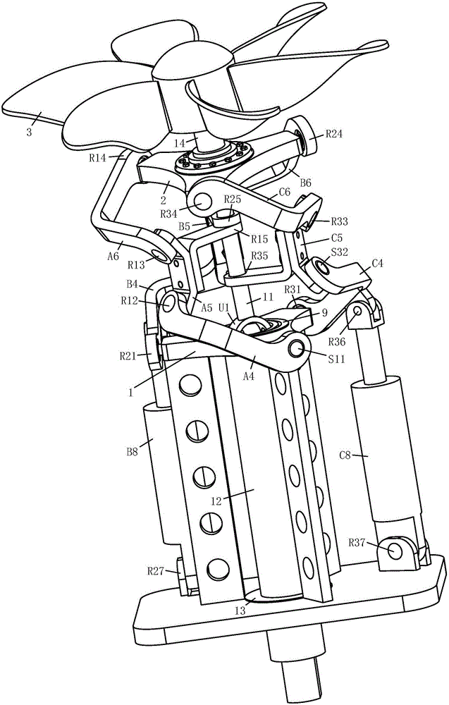
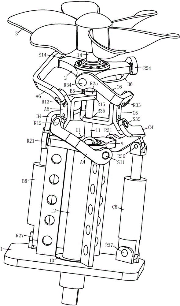
[0024] like figure 1 , figure 2 and Figure 5 As shown, it is the first embodiment disclosed by the present invention, a parallel underwater vector thruster, which mainly includes a frame 1, a reversing table 2, three motion branch chains connecting the frame 1, and the reversing table 2, and the three motions The specific connection method of the branch chain is as follows:

[0025] The first motion branch chain is composed of lower link A4, middle link A5 and upper link A6. One end of the lower link A4 is connected to the frame 1 through the ball pair S11, and the other end of the lower link A4 is connected to the middle link A5. Connected by the rotating pair R12, one end of the upper link A6 is connected with the middle connecting rod A5 through the rotating pair R13, and the other end of the upper connecting rod A6 is connected with the reversing table 2 through the rotating pair R14; the second kinematic branch chain is connected by the lower link B4 , the middle lin...

Embodiment 2

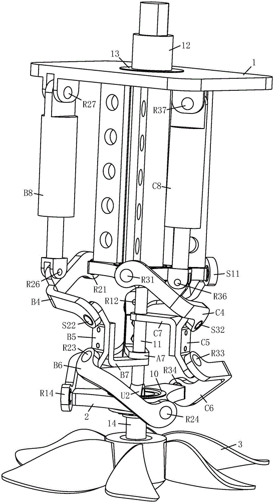
[0031] like image 3 , Figure 4 and Figure 5 As shown, it is the second embodiment disclosed by the present invention, a parallel underwater vector thruster, which mainly includes frame 1, reversing table 2, three motion branch chains connecting frame 1 and reversing table 2, and three motion The specific connection method of the branch chain is as follows:

[0032] The first motion branch chain is composed of lower link A4, middle link A5 and upper link A6. One end of the lower link A4 is connected to the frame 1 through the ball pair S11, and the other end of the lower link A4 is connected to the middle link A5. Connected by the rotary pair R12, one end of the upper link A6 is connected with the middle link A5 through the rotary pair R13, and the other end of the upper link A6 is connected with the reversing table 2 through the ball pair S14; the second kinematic branch chain is connected by the lower link B4 , the middle link B5 and the upper link B6, one end of the lo...


PUM


Abstract

A parallel type underwater vectored thruster mainly comprises a machine frame, a turning machine and three movement branch chains for connecting the machine frame with the turning machine. Each movement branch chain is composed of a lower connection rod, a middle connection rod and an upper connection rod, wherein the lower connection rod and the machine frame are connected through a rotary pair or a sphere pair; the lower connection rod and the middle connection rod are connected through a rotary pair or a sphere pair; the middle connection rod and the upper connection rod are connected through a rotary pair; and the upper connection rod and the turning machine are connected through a rotary pair or a sphere pair. The three movement branch chains are connected with one another through three coupling connection rods and one center connection rod, one end of each coupling connection rod is fixedly connected with the middle connection rod of the corresponding movement branch chain, and the other end of each coupling connection rod is connected with the center connection rod through a rotary pair. Two-freedom-degree rotation of the turning machine relative to the machine frame can be achieved, the parallel type underwater vectored thruster has the advantages of being small in size, large in rigidity, high in precision, large in rotary working space and the like, and the parallel type underwater vectored thruster can be widely applied to ship thrust systems.

Description

technical field [0001] The invention relates to a vector thruster, in particular to a parallel underwater vector thruster. technical background [0002] At present, the vehicles used for underwater observation, investigation and development mainly include manned submersibles and unmanned submersibles. and mobility put forward higher requirements. In this context, the submersible using the traditional fin-rudder control method has been unable to meet the task requirements to a certain extent, especially when the maneuverability of the rudder is significantly weakened when moving at low speed. In order to improve the flexibility of the submersible, developing a new type of submersible with a vector thruster is one of the effective solutions. [0003] Vector propulsion is also called thrust steering technology, which means that the propulsion system of a space moving object can not only provide forward thrust, but also simultaneously or separately provide thrust and torque in...

Claims


Application Information

Patent Timeline
Patent Type & Authority Applications(China)
IPC IPC(8): B63G8/08
CPCB63G8/08
Inventor 褚宏鹏孙通帅
Owner 褚宏鹏
Why Eureka
Try Eureka