Outer rotor of motor for traction machine

A motor traction machine and outer rotor technology, applied in electromechanical devices, mechanical energy control, electrical components, etc., can solve the unfavorable special environment with strict requirements on the thickness of the traction machine, long axial length of the traction machine, management and maintenance costs Advanced problems, to achieve the effect of easy management and maintenance, filling technical gaps, and reducing processing costs

Active Publication Date: 2016-08-10
曾海平
View PDF6 Cites 9 Cited by
  • Summary
  • Abstract
  • Description
  • Claims
  • Application Information

AI Technical Summary

Problems solved by technology

[0003] In the prior art, the common structure of the traction machine is as follows figure 1 As shown, in the structure of this type of traditional traction machine, the traction sheave 2 and the motor 3 are independently designed and arranged independently, resulting in a long axial length and a large thickness of the traction machine, which is not conducive to affecting the thickness of the traction machine. Special environments with strict requirements—such as the installation and configuration of machine room-less elevators, and the utilization rate of materials is low, there are many product parts, the processing and installation are complicated, and the management and maintenance costs are high

Method used


Image

  • Outer rotor of motor for traction machine
  • Outer rotor of motor for traction machine
  • Outer rotor of motor for traction machine

Examples


Embodiment Construction

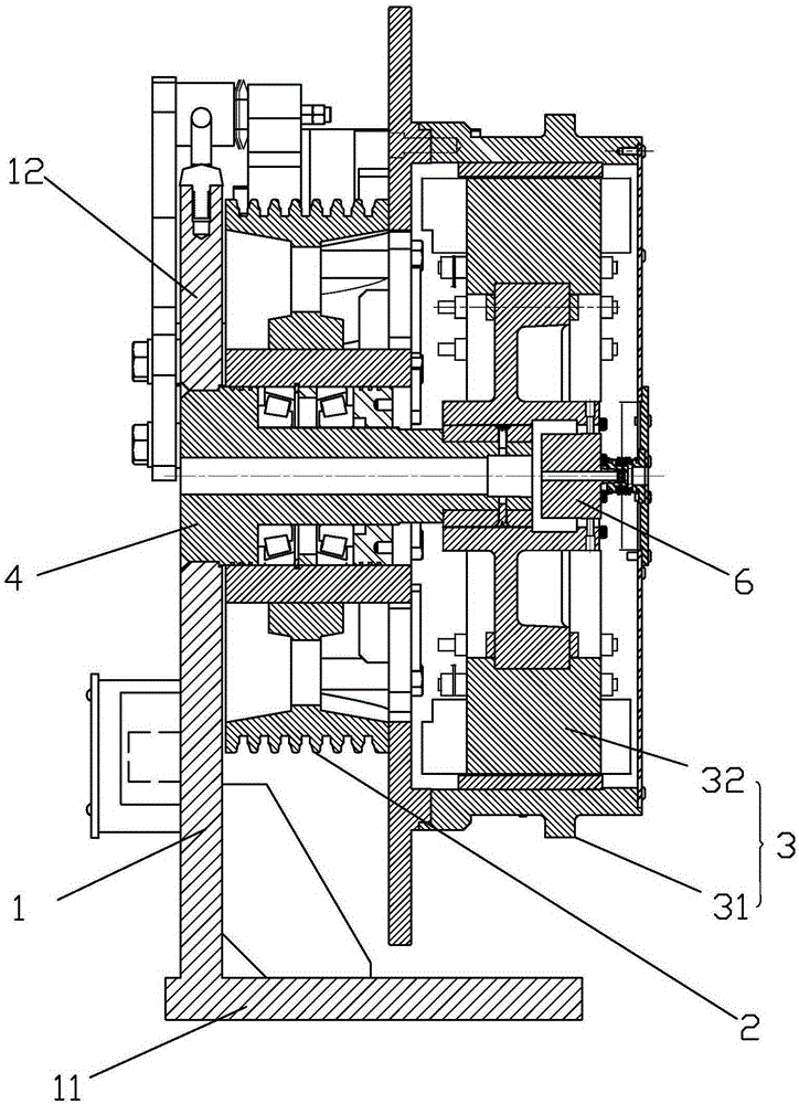
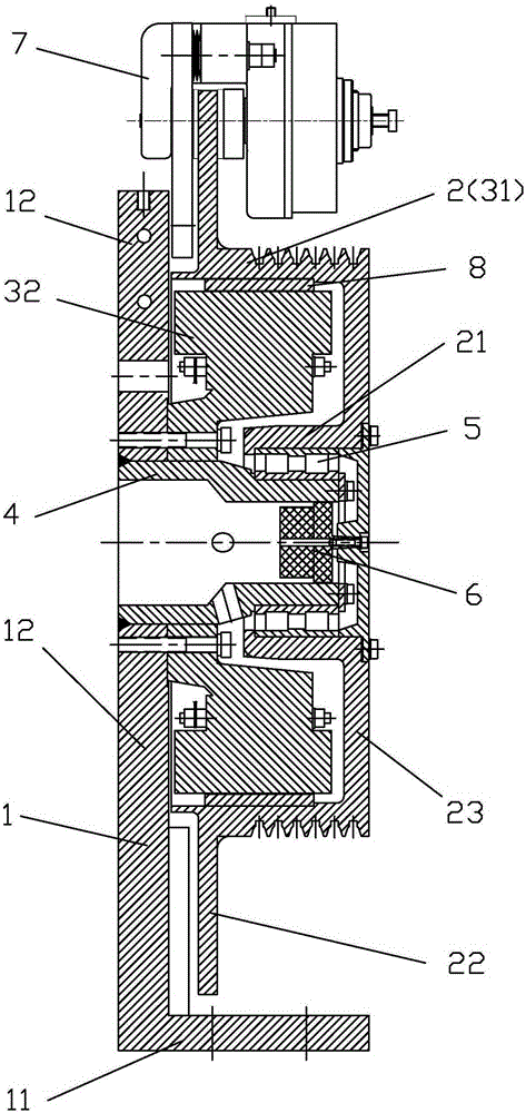
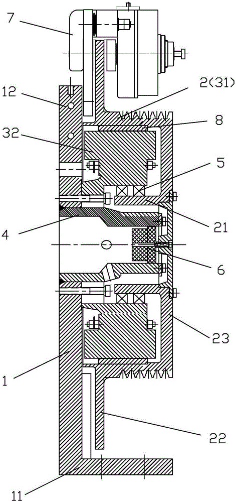
[0016] refer to Figure 2 to Figure 4 , an outer rotor motor traction machine, including a machine base 1, a traction wheel 2 arranged on the machine base 1, and a motor 3 that drives the traction machine to rotate, the said machine base 1 is composed of a bottom plate 11 and a vertical plate 12, the inner end surface of the vertical plate 12 is fixedly provided with a support shaft 4 parallel to the bottom plate 12, one end of which is fixed on the vertical plate 12, and the other end is suspended, and the inner wall of the traction wheel 2 is fixedly provided with a permanent magnet 8 so that The motor rotor 31 and the traction wheel 2 are combined into one, the motor stator 32 is fixed on the vertical plate 12, the traction wheel 2 has an end face 23, the motor stator 32 is located between the vertical plate 12 and the end face 23, and the end face of the traction wheel 23 extends a rotating shaft 21 toward the supporting shaft 4 to make the traction sheave 2 rotate around ...


PUM


Abstract

The invention discloses an outer rotor of a motor for a traction machine. The outer rotor comprises a machine seat, a traction wheel arranged on the machine seat, and the motor driving the traction machine to rotate. The machine seat is composed of a bottom plate and a vertical plate, both of which are vertically arranged. The inner end surface of the vertical plate is fixedly provided with a support shaft parallel to the bottom plate. One end of the support shaft is fixed on the vertical plate and the other end of the support plate is suspended. The inner wall of the traction wheel is fixedly provided with a permanent magnet such that the motor rotor and the traction wheel are combined as one. A motor stator is fixed on the vertical plate. The traction wheel has an end surface. The motor stator is positioned between the vertical plate and an end surface. A rotary shaft extends out of the position, facing the support shaft, of the end surface of the traction wheel such that the traction wheel rotates around the support shaft. The rotary shaft is axially overlapped with the support shaft. The outer rotor of the motor for the traction machine has following beneficial effects: by means of the traction wheel, the motor rotor, the rotary shaft of the traction wheel and the support shaft of the machine seat, axial overlap can be achieved. The axial thickness of the traction wheel is shortened so that the ultra-thin design is realized. Cost is reduced and the installation process is simplified. Management and maintenance are conveniently carried out. The final-period maintenance cost of an elevator is decreased.

Description

technical field [0001] The invention relates to a power device of an elevator, in particular to an outer rotor motor traction machine. Background technique [0002] The traction machine is the power equipment of the elevator, and its function is to convey and transmit power to make the elevator run. During operation, the rotation of the motor drives the traction sheave to rotate, and the wire rope on the traction sheave drags the car and the counterweight to move relative to each other, so that the car reciprocates up and down along the guide rail in the hoistway to complete the transportation of the elevator. [0003] In the prior art, the common structure of the traction machine is as follows figure 1 As shown, in the structure of this type of traditional traction machine, the traction sheave 2 and the motor 3 are independently designed and arranged independently, resulting in a long axial length and a large thickness of the traction machine, which is not conducive to aff...

Claims


Application Information

Patent Timeline
Patent Type & Authority Applications(China)
IPC IPC(8): B66B11/04
CPCB66B11/0438H02K7/102
Inventor 曾海平
Owner 曾海平
Why Eureka
Try Eureka