Ballast transverse and lengthways accelerated speed coupling detection apparatus and integrated detection system

A vertical acceleration and detection device technology, which is applied in the direction of measuring devices, machine/structural component testing, instruments, etc., can solve the problems of high risk of detection tasks, cumbersome layout of data transmission lines, inaccurate data measurement values, etc., and achieve saving Effects of Disk Space, Guaranteeing Authenticity, and Improving Accuracy

Active Publication Date: 2016-08-10
CENT SOUTH UNIV +1
View PDF8 Cites 1 Cited by
  • Summary
  • Abstract
  • Description
  • Claims
  • Application Information

AI Technical Summary

Problems solved by technology

[0009] The purpose of the present invention is to overcome the problems of inaccurate data measurement values, high risk of detection tasks, and cumbersome layout of data transmission lines in conventional detection methods, provide an accurate ballast acceleration detection method, and realize the start and end of electronic induction control detection and Integrated detection system for wireless transmission of different parts of track-bridge-foundation

Method used


Image

  • Ballast transverse and lengthways accelerated speed coupling detection apparatus and integrated detection system
  • Ballast transverse and lengthways accelerated speed coupling detection apparatus and integrated detection system
  • Ballast transverse and lengthways accelerated speed coupling detection apparatus and integrated detection system

Examples


Embodiment Construction

[0067] The technical content of the present invention will be further described below, but it is not intended to limit the essential content of the present invention.

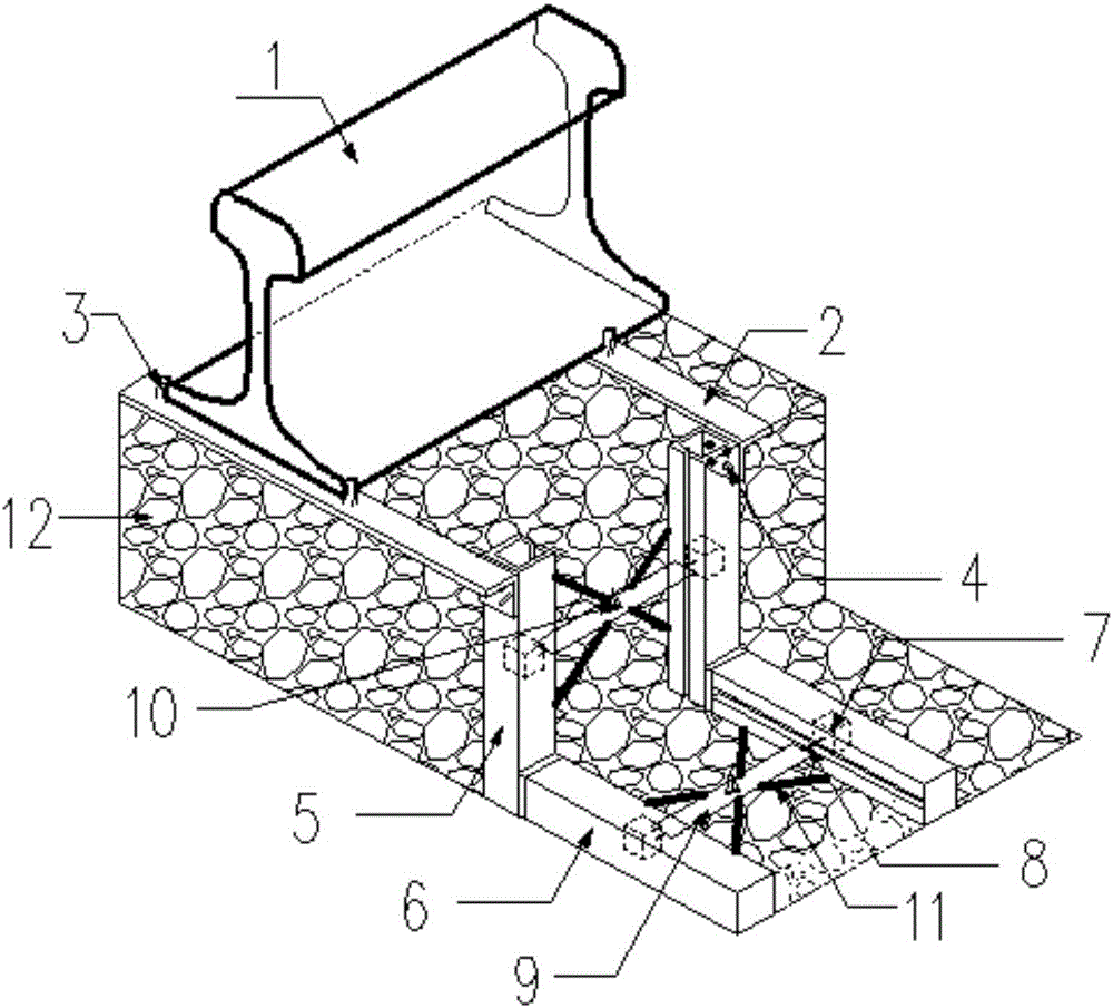
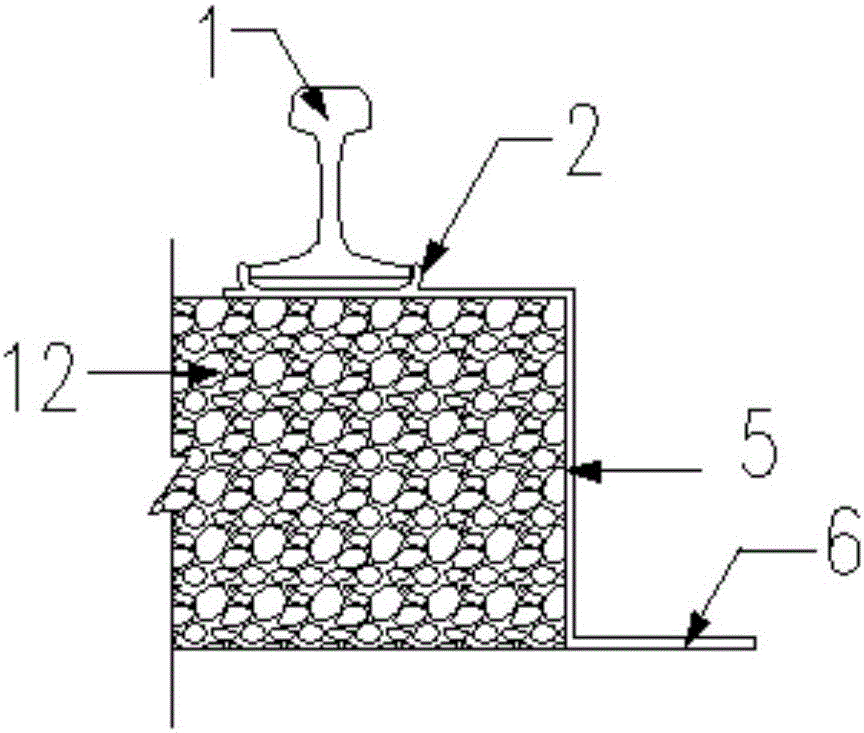
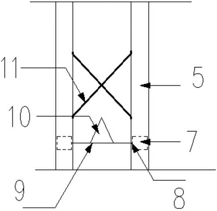
[0068] figure 1 It is the diagram of ballast horizontal and vertical acceleration coupling detection device; figure 2 It is the detailed side elevation view of ballast horizontal and vertical acceleration coupling detection device; image 3 It is the detailed diagram of the stiffening structure of the inner side of the vertical limit track; Figure 4 It is a schematic diagram of the bolt connection between the horizontal steel plate and the vertical limit track; Figure 5 It is a three-dimensional schematic diagram of the connection between the vertical limit track and the horizontal installation track (light slider); Figure 6 It is a top view of the connection between the vertical limit rail and the limit plate; Figure 7 It is the detailed drawing of the horizontal installation track structure; Figure...


PUM


Abstract

The invention discloses a ballast transverse and lengthways accelerated speed coupling detection apparatus and a track-bridge-base integrated detection system. The ballast transverse and lengthways accelerated speed coupling detection apparatus comprises a horizontal steel plate used as a fixed substrate, wherein the horizontal steel plate is laid between a steel rail and ballast, the horizontal steel plate is clamped and fixed on a bottom part of the steel rail along a horizontal direction, the bottom part of the horizontal steel plate is fixedly connected with a lengthways accelerated speed coupling detection mechanism which is positioned in the ballast and used for simulating ballast lengthways accelerated speed and a horizontal accelerated speed coupling detection mechanism which is fixedly connected onto a bottom part of the lengthways accelerated speed coupling detection mechanism and used for simulating ballast horizontal accelerated speed. The ballast transverse and lengthways accelerated speed coupling detection apparatus is advantaged by convenience of disassembling operation, high measuring precision, lightweight, structure and function integration and the like. The ballast transverse and lengthways accelerated speed coupling detection apparatus can be used as a high precision sensing apparatus applied to the track-bridge-base integrated detection system, artificial simulated organic ballast is convenient and simple to make and can be used in a cyclic manner under the same geological conditions, and results can conform to real force born by the ballast; a detection method of the ballast transverse and lengthways accelerated speed coupling detection apparatus is technically reliable and economically reasonable, and convenience of construction is realized.

Description

technical field [0001] The invention relates to the technical field of railway track detection, in particular to a ballast horizontal and vertical acceleration coupling detection device. In addition, the present invention also relates to a track-bridge-foundation integrated detection system using ballast horizontal and vertical acceleration coupling detection devices. Background technique [0002] As the throat and transportation hub of the line, the bridge is an important part of accelerating the pace of my country's economic development and modernization. With the passage of time, the bridge itself, the basic structure supporting the bridge, and the track structure laid on the bridge will inevitably suffer from structural damage and defects of varying degrees under the action of the natural environment, increased traffic volume and traffic load. [0003] Especially for the existing ballasted track, bridge and corresponding infrastructure in our country, because the design...

Claims


Application Information

Patent Timeline
Patent Type & Authority Applications(China)
IPC IPC(8): G01M99/00
CPCG01M99/004
Inventor 吴玲玉余志武谈遂毛建锋金城李海燕
Owner CENT SOUTH UNIV
Why Eureka
Try Eureka