Attitude control thruster layout optimization method for combined spacecraft

A thruster layout and combined spacecraft technology, which is applied in the field of satellite attitude control, can solve the problems of thruster layout optimization, etc., and achieve the effect of prolonging the working life of the orbit and reducing fuel consumption

Active Publication Date: 2016-08-10
BEIJING INSTITUTE OF TECHNOLOGYGY +1
7 Cites 31 Cited by

AI-Extracted Technical Summary

Problems solved by technology

However, these two methods are all researches on a single spacecraft, and there is little research on the thruster ...

Abstract

The invention relates to an attitude control thruster layout optimization method for a combined spacecraft and belongs to the technical field of satellite attitude control. According to the method, firstly, a thruster is obliquely mounted; secondly, a universal joint with two freedoms is additionally mounted at a joint portion of the thruster; thirdly, a thruster thrust distribution model is designed under constraints of minimum fuel consumption and a universal joint rotation angle according to a desired control torque; lastly, according to an attitude angle and attitude angle speed change fed back by a sensor, the opening/closing and blowing duration of the thruster is controlled through a phase plane control method. Rapid attitude maneuvering of the spacecraft is realized, fuel consumption is reduced, and a complete control circuit is formed. Through the method, a blowing direction of the thruster is driven to change on the basis of rotation of the universal joint, a problem of unstable control caused by large-scale mass center offset because of rendezvous and docking is effectively solved; fuel consumption can be reduced, and on-orbit service life of the thruster is prolonged.

Application Domain

Technology Topic

Satellite attitude controlSpacecraft +8

Image

  • Attitude control thruster layout optimization method for combined spacecraft
  • Attitude control thruster layout optimization method for combined spacecraft
  • Attitude control thruster layout optimization method for combined spacecraft

Examples

  • Experimental program(1)

Example Embodiment

[0149] The present invention will be further described below in conjunction with the accompanying drawings and embodiments.
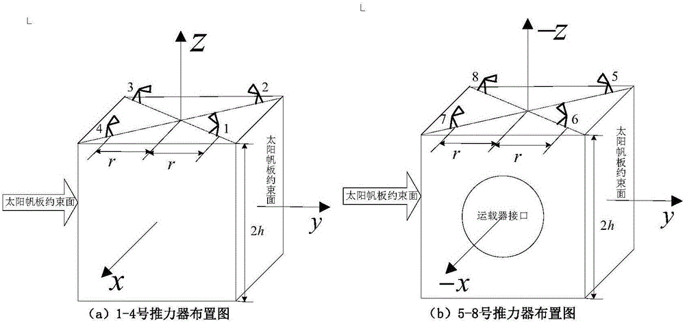
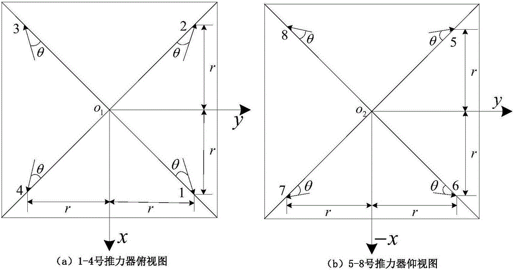
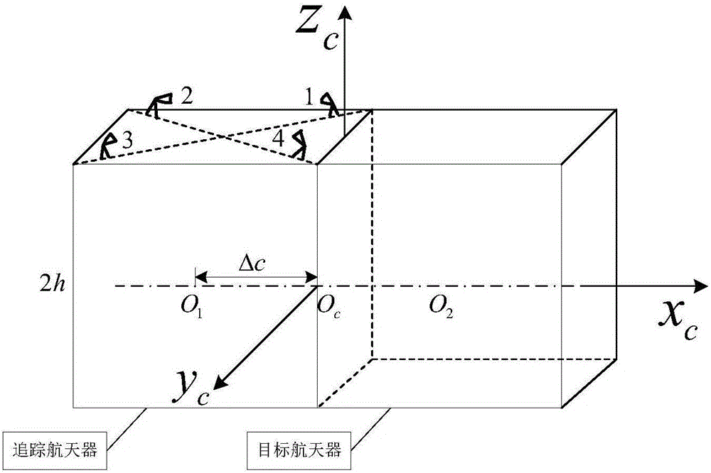
[0150] A method for optimizing the layout of a combined spacecraft attitude control thruster according to the present invention takes a tracking spacecraft in the shape of a cube (2m×2m×2m) as the research object, which has the same shape as the target satellite it docks with. The tracking spacecraft is configured as figure 1 , figure 2 As shown, the configuration of the combined spacecraft after rendezvous and docking is as follows image 3 shown.
[0151] The rotation mode of the universal joint installed at the joint of the thruster is as follows: Figure 4 , Figure 5 shown. The universal joints are installed on the thrusters 1, 2, 1 and 2 of the combined spacecraft respectively, and the simulation is carried out according to the different rotation modes of the universal joints.
[0152] Its simulation parameters are as follows:
[0153] Table 1 Simulation parameter table
[0154]
[0155] The comparison between the simulation results and the amount of fuel consumed by the three-axis attitude stabilization control of the assembly without universal joints is as follows:
[0156] Table 2 Three-axis fuel consumption and total consumption in each case
[0157]
[0158] The described method for optimizing the layout of thrusters for combined spacecraft attitude control, the specific steps are as follows:
[0159] Step 1. Determine the thruster installation layout of the tracking spacecraft
[0160] For three-axis stabilized satellites, the thrusters are mainly arranged on the surface of the star, and the constraints restricted by the system design requirements mainly include the following aspects:
[0161] (1) The interface relationship with the launch vehicle;
[0162] (2) The installation surface of the solar panel;
[0163] (3) Installation location and functional requirements of other catalog payloads, such as antennas and various sensors;
[0164] (4) Interface relationship with star structure system, control system, power supply system, thermal control system, etc.
[0165] Therefore, the position matrix composed of all thrusters in the body coordinate system can be obtained as:
[0166] d = r - r - r r r - r - r r r r - r - r r r - r - r h h h h - h - h - h - h - - - ( 1 )
[0167] r is the position of the thruster in the x and y directions in the spacecraft body coordinate system, and h is the position in the z direction, which is also the side length of the spacecraft.
[0168] The direction matrix of each thruster is:
[0169] e = c β c Δ - c β c Δ - c β c Δ c β c Δ c β s Δ - c β s Δ - c β s Δ c β s Δ c β s Δ c β s Δ - c β s Δ - c β s Δ c β c Δ - c β c Δ - c β c Δ c β c Δ - s β - s β - s β - s β s β s β s β s β - - - ( 2 )
[0170] According to the designed satellite configuration, considering the influence of the plume, the value range of θ is limited:
[0171] 0
[0172] Where Δ=45°-θ, c(Ω)=cosΩ, s(Ω)=sinΩ.
[0173] When each thruster produces unit thrust, the composed moment matrix is:
[0174] A = d × e = [ - r s β - h c β s Δ - r s β - h c β s Δ r s β + h c β s Δ r s β + h c β s Δ r s β + h c β c Δ - r s β - h c β c Δ - r s β - h c β c Δ r s β + h c β c Δ r c β s Δ - r c β c Δ - r c β s Δ + r c β c Δ r c β s Δ - r c β c Δ - r c β s Δ + r c β c Δ r s β + h c β c Δ r s β - h c β c Δ - r s β - h c β c Δ - r s β + h c β c Δ - r s β - h c β s Δ r s β + h c β s Δ r s β + h c β s Δ - r s β - h c β s Δ - r s β - h c β s Δ r c β c Δ + r c β s Δ - r c β s Δ + r c β c Δ r c β c Δ + r c β s Δ - - - ( 4 )
[0175] In the formula, β is the angle between each thruster and the surface of the star, and θ is the angle between the jet direction of the thruster and the diagonal of the cube surface.
[0176] Step 2. After determining the rendezvous and docking of the spacecraft, combine the spacecraft thruster layout
[0177] After the rendezvous and docking, the position of the center of mass of the combined spacecraft changes, and the change of the center of mass Δc can be obtained by identifying the mass characteristics of the combined body.
[0178] Therefore, the installation position of the thruster in the combined spacecraft body coordinate system can be obtained as:
[0179] d c = r - h - r - h - r - h r - h r - h - r - h - r - h r - h r r - r - r r r - r - r h h h h - h - h - h - h - - - ( 5 )
[0180] The direction matrix of each thruster is formula (2);
[0181] The moment matrix of the unit thrust of the thruster to the assembly is:
[0182] A c = d c × e = [ - r s β - h c β s Δ - r s β - h c β s Δ r s β + h c β s Δ r s β + h c β s Δ h c β c Δ - ( h - r ) s β - ( h + r ) s β - h c β c Δ - ( h + r ) s β - h c β c Δ h c β c Δ - ( h - r ) s β - r c β c Δ - ( h - r ) c β s Δ r c β c Δ - ( h + r ) c β s Δ ( h + r ) c β s Δ - r c β c Δ r c β c Δ + ( h - r ) c β s Δ r s β + h c β c Δ r s β - h c β c Δ - r s β - h c β c Δ h c β c Δ - r s β ( h - r ) s β - h c β s Δ ( h + r ) s β + h c β s Δ ( h + r ) s β + h c β s Δ ( h - r ) s β - h c β s Δ - r c β s Δ - ( h - r ) c β c Δ ( h + r ) c β c Δ + r c β s Δ ( h + r ) c β c Δ - r c β s Δ r c β s Δ - ( h - r ) c β c Δ - - - ( 6 )
[0183] Step 3. Obtain the changed thruster layout based on the rotation of the universal joint
[0184] One of the thrusters is selected, and a universal joint with two degrees of freedom is installed at its joint. Through the rotation of the universal joint, the jet direction of the thruster is driven, that is, the β and θ are changed. Consider several installation scenarios:
[0185] Situation 1: select the thruster-1 which is closer to the center of mass of the assembly, and make the universal joint rotate with a single degree of freedom, that is, change the β and θ of the jet direction respectively;
[0186] (1) Control the change of β angle
[0187] The direction matrix of the thruster is:
[0188] e β 1 = cβ 1 c Δ - c β c Δ - c β c Δ c β c Δ c β s Δ - c β s Δ - c β s Δ c β s Δ cβ 1 s Δ c β s Δ - c β s Δ - c β s Δ c β c Δ - c β c Δ - c β c Δ c β c Δ - sβ 1 - s β - s β - s β s β s β s β s β - - - ( 7 )
[0189] The unit moment matrix of the thruster is:
[0190] A β 1 = d c × e β 1 = [ - rsβ 1 - hcβ 1 s Δ - r s β - h c β s Δ r s β + h c β s Δ r s β + h c β s Δ hcβ 1 c Δ - ( h - r ) sβ 1 - ( h + r ) s β - h c β c Δ - ( h + r ) s β - h c β c Δ h c β c Δ - ( h - r ) s β - rcβ 1 c Δ - ( h - r ) cβ 1 s Δ r c β c Δ - ( h + r ) c β s Δ ( h + r ) c β s Δ - r c β c Δ r c β c Δ + ( h - r ) c β s Δ r s β + h c β c Δ r s β - h c β c Δ - r s β - h c β c Δ h c β c Δ - r s β ( h - r ) s β - h c β s Δ ( h + r ) s β + h c β s Δ ( h + r ) s β + h c β s Δ ( h - r ) s β - h c β s Δ - r c β s Δ - ( h - r ) c β c Δ ( h + r ) c β c Δ + r c β s Δ ( h + r ) c β c Δ - r c β s Δ r c β s Δ - ( h - r ) c β c Δ - - - ( 8 )
[0191] (2) Control the change of θ (ie Δ) angle
[0192] The direction matrix of the thruster is:
[0193] e Δ 1 = cβcΔ 1 - c β c Δ - c β c Δ c β c Δ c β s Δ - c β s Δ - c β s Δ c β s Δ cβsΔ 1 c β s Δ - c β s Δ - c β s Δ c β c Δ - c β c Δ - c β c Δ c β c Δ - s β - s β - s β - s β s β s β s β s β - - - ( 9 )
[0194] The unit moment matrix of the thruster is:
[0195] A Δ 1 = d c × e Δ 1 = [ - r s β - hcβsΔ 1 - r s β - h c β s Δ r s β + h c β s Δ r s β + h c β s Δ hcβcΔ 1 - ( h - r ) s β - ( h + r ) s β - h c β c Δ - ( h + r ) s β - h c β c Δ h c β c Δ - ( h - r ) s β - rcβcΔ 1 - ( h - r ) cβsΔ 1 r c β c Δ - ( h + r ) c β s Δ ( h + r ) c β s Δ - r c β c Δ r c β c Δ + ( h - r ) c β s Δ r s β + h c β c Δ r s β - h c β c Δ - r s β - h c β c Δ h c β c Δ - r s β ( h - r ) s β - h c β s Δ ( h + r ) s β + h c β s Δ ( h + r ) s β + h c β s Δ ( h - r ) s β - h c β s Δ - r c β s Δ - ( h - r ) c β c Δ ( h + r ) c β c Δ + r c β s Δ ( h + r ) c β c Δ - r c β s Δ r c β s Δ - ( h - r ) c β c Δ - - - ( 10 )
[0196] Case 2: select thruster 2 2 which is far away from the center of mass of the combined body, control the single-degree-of-freedom rotation of the universal joint, and change the jet direction β and θ respectively.
[0197] (1) Control the change of β angle
[0198] The direction matrix of the thruster is:
[0199] e β 2 = c β c Δ - cβ 2 c Δ - c β c Δ c β c Δ c β s Δ - c β s Δ - c β s Δ c β s Δ c β s Δ cβ 2 s Δ - c β s Δ - c β s Δ c β c Δ - c β c Δ - c β c Δ c β c Δ - s β - sβ 2 - s β - s β s β s β s β s β - - - ( 11 )
[0200] The unit moment matrix of the thruster is:
[0201] A β 2 = d c × e β 2 = [ - r s β - h c β s Δ - rsβ 2 - hcβ 2 s Δ r s β + h c β s Δ r s β + h c β s Δ h c β c Δ - ( h - r ) s β - ( h + r ) sβ 2 - hcβ 2 c Δ - ( h + r ) s β - h c β c Δ h c β c Δ - ( h - r ) s β - r c β c Δ - ( h - r ) c β s Δ rcβ 2 c Δ - ( h + r ) cβ 2 s Δ ( h + r ) c β s Δ - r c β c Δ r c β c Δ + ( h - r ) c β s Δ r s β + h c β c Δ r s β - h c β c Δ - r s β - h c β c Δ h c β c Δ - r s β ( h - r ) s β - h c β s Δ ( h + r ) s β + h c β s Δ ( h + r ) s β + h c β s Δ ( h - r ) s β - h c β s Δ - r c β s Δ - ( h - r ) c β c Δ ( h + r ) c β c Δ + r c β s Δ ( h + r ) c β c Δ - r c β s Δ r c β s Δ - ( h - r ) c β c Δ - - - ( 12 )
[0202] (2) Control the change of θ (ie Δ) angle
[0203] The direction matrix of the thruster is:
[0204] e Δ 2 = c β c Δ - cβcΔ 2 - c β c Δ c β c Δ c β s Δ - c β s Δ - c β s Δ c β s Δ c β s Δ cβsΔ 2 - c β s Δ - c β s Δ c β c Δ - c β c Δ - c β c Δ c β c Δ - s β - s β - s β - s β s β s β s β s β - - - ( 13 )
[0205] The unit moment matrix of the thruster is:
[0206] A Δ 2 = d c × e Δ 2 = [ - r s β - h c β s Δ - r s β - hcβsΔ 2 r s β + h c β s Δ r s β + h c β s Δ h c β c Δ - ( h - r ) s β - ( h + r ) s β - hcβcΔ 2 - ( h + r ) s β - h c β c Δ h c β c Δ - ( h - r ) s β - r c β c Δ - ( h - r ) c β s Δ rcβcΔ 2 - ( h + r ) cβsΔ 2 ( h + r ) c β s Δ - r c β c Δ r c β c Δ + ( h - r ) c β s Δ r s β + h c β c Δ r s β - h c β c Δ - r s β - h c β c Δ h c β c Δ - r s β ( h - r ) s β - h c β s Δ ( h + r ) s β + h c β s Δ ( h + r ) s β + h c β s Δ ( h - r ) s β - h c β s Δ - r c β s Δ - ( h - r ) c β c Δ ( h + r ) c β c Δ + r c β s Δ ( h + r ) c β c Δ - r c β s Δ r c β s Δ - ( h - r ) c β c Δ - - - ( 14 )
[0207] Situation 3: select thruster one 1 and thruster two 2 at the same time, install universal joints at their joints, and control the jet directions β and θ.
[0208] (1) Control the change of β angle
[0209] The direction matrix of the thruster is:
[0210] e β 12 = cβ 1 c Δ - cβ 2 c Δ - c β c Δ c β c Δ c β s Δ - c β s Δ - c β s Δ c β s Δ cβ 1 s Δ cβ 2 s Δ - c β s Δ - c β s Δ c β c Δ - c β c Δ - c β c Δ c β c Δ - sβ 1 - sβ 2 - s β - s β s β s β s β s β - - - ( 15 )
[0211] The unit moment matrix of the thruster is:
[0212] A β 12 = d c × e β 12 = [ - rsβ 1 - hcβ 1 s Δ - rsβ 2 - hcβ 2 s Δ r s β + h c β s Δ r s β + h c β s Δ hcβ 1 c Δ - ( h - r ) sβ 1 - ( h + r ) sβ 2 - hcβ 2 c Δ - ( h + r ) s β - h c β c Δ h c β c Δ - ( h - r ) s β - rcβ 1 c Δ - ( h - r ) cβ 1 s Δ rcβ 2 c Δ - ( h + r ) cβ 2 s Δ ( h + r ) c β s Δ - r c β c Δ r c β c Δ + ( h - r ) c β s Δ r s β + h c β c Δ r s β - h c β c Δ - r s β - h c β c Δ h c β c Δ - r s β ( h - r ) s β - h c β s Δ ( h + r ) s β + h c β s Δ ( h + r ) s β + h c β s Δ ( h - r ) s β - h c β s Δ - r c β s Δ - ( h - r ) c β c Δ ( h + r ) c β c Δ + r c β s Δ ( h + r ) c β c Δ - r c β s Δ r c β s Δ - ( h - r ) c β c Δ - - - ( 16 )
[0213] (2) Control the change of θ (ie Δ) angle
[0214] The direction matrix of the thruster is:
[0215] e Δ 12 = cβcΔ 1 - cβcΔ 2 - c β c Δ c β c Δ c β s Δ - c β s Δ - c β s Δ c β s Δ cβsΔ 1 cβsΔ 2 - c β s Δ - c β s Δ c β c Δ - c β c Δ - c β c Δ c β c Δ - s β - s β - s β - s β s β s β s β s β - - - ( 17 )
[0216] The unit moment matrix of the thruster is:
[0217] A Δ 12 = d c × e Δ 12 = [ - r s β - hcβsΔ 1 - r s β - hcβsΔ 2 r s β + h c β s Δ r s β + h c β s Δ hcβcΔ 1 - ( h - r ) s β - ( h + r ) s β - hcβcΔ 2 - ( h + r ) s β - h c β c Δ h c β c Δ - ( h - r ) s β - rcβcΔ 1 - ( h - r ) cβsΔ 1 rcβcΔ 2 - ( h + r ) cβsΔ 2 ( h + r ) c β s Δ - r c β c Δ r c β c Δ + ( h - r ) c β s Δ r s β + h c β c Δ r s β - h c β c Δ - r s β - h c β c Δ h c β c Δ - r s β ( h - r ) s β - h c β s Δ ( h + r ) s β + h c β s Δ ( h + r ) s β + h c β s Δ ( h - r ) s β - h c β s Δ - r c β s Δ - ( h - r ) c β c Δ ( h + r ) c β c Δ + r c β s Δ ( h + r ) c β c Δ - r c β s Δ r c β s Δ - ( h - r ) c β c Δ - - - ( 18 )
[0218] Step 4. According to the expected moment of three-axis attitude stability, design the thruster control distribution model with the minimum fuel consumption and the rotation angle of the gimbal as constraints
[0219] In spacecraft control, the system state-space model is written as:
[0220] x = T x + a d + d r y = C x - - - ( 19 )
[0221] where x∈R m is the system state quantity, d r ∈ R m is the disturbance term; a d ∈ R m is the control command given by the controller, that is, the expected torque A in different situations in step 3 β1 ,A Δ1 ,A β2 ,A Δ2 ,A β12 ,A Δ12;y∈R k Is the observation vector, T and C are the state parameters.
[0222] During the attitude control of the spacecraft by the thruster, the
[0223] a d =BF(20)
[0224] In the formula, F=[F 1 ,...,F n ] T , each element of which represents the thrust of each thruster; B is an m×n order matrix, which is the thruster efficiency matrix. For the thrust of the i-th thruster, the constraint 0≤F is satisfied i ≤F imax (i=1,...,n). The problem of finding the optimal solution F in this step is the control assignment problem.
[0225] For several different situations in Step 3, two control allocation models can be established, which are respectively constrained by β and θ.
[0226] (1) Constrained by β
[0227] min F 1 + F 2 + ... + F n s . t . a d = B F 0 ≤ F i ≤ F i max 0 ≤ β ≤ π - - - ( 21 )
[0228] (2) Constrained by θ
[0229] min F 1 + F 2 + ... + F n s . t . a d = B F 0 ≤ F i ≤ F i max 0 θ π 4 - - - ( 22 )
[0230] The optimized thrust of each thruster can be obtained from Equation (21) and Equation (22), which is fed back to the spacecraft dynamics to obtain the attitude angle and attitude angular velocity.
[0231] Step 5. Based on the attitude angle and attitude angular velocity obtained in step 4, design the phase plane controller, control the thruster on/off and jet duration, and obtain the desired control torque of the spacecraft
[0232] Since the tracking spacecraft adopts a three-axis attitude-stabilizing jet system, the attitude angle is small and the attitude angular velocity is much smaller than the orbital angular velocity in the case of stable control, so the small quantity and disturbance moment above the second order can be ignored, and the attitude dynamics equation It can be further simplified to a fully decoupled form of the three-axis dynamic equations.
[0233] For this typical second-order system, the phase plane composed of attitude angle and attitude angular velocity can be used to design the control law. The phase plane diagram designed by the present invention is symmetrical about the origin, and is illustrated with the negative phase plane of the right half plane.
[0234] (1)R 1 Zone: When the conditions are met and , the phase point is at R 1 zone, the engine is turned on in negative phase, and the jet length is T r1; This area is a long spray area, and its effect is to eliminate the large initial attitude angle and attitude angle rate deviation of damping with the jet of longer time; Said engine refers to all the thrusters that are opened in step 4; that is, the thrust is not zero the thruster;
[0235] (2) R 2 Zone: When the conditions are met and , the phase point is at R 2 zone, the engine is turned on in negative phase, and the jet length is T r2; This area is the middle spray area, which is used to speed up the convergence speed of the attitude angle and the attitude angle rate;
[0236] (3)R 3 Zone: When the conditions are met and , the phase point is at R 3 zone, the engine is turned on in negative phase, and the jet length is T r3; This area is a short injection area, the engine injection time in this area is relatively short, which is used to damp the external disturbance torque and form a long-term unilateral limit cycle;
[0237] (4)R 4 Zone: When the conditions are met and , the phase point is at R 4 zone, the engine is turned on in positive phase, and the jet length is T r4; This area is the rate damping area, its function is to suppress the increase of the attitude angle rate and accelerate the convergence of the attitude angle error.
[0238] R' in the left half plane 1 ,R′ 2 ,R' 3 ,R' 4 corresponding to R 1 , R 2 , R 3 , R 4 , but the jet direction of the engine is opposite.
[0239] The boundary of each area is determined by the vertical switch line l1-l6 and the switch line f1-f10, among which, l1 and l2 determine the boundary of the unilateral limit cycle, that is, determine the control accuracy of the phase plane, and its parameters should be based on the attitude control task. The accuracy should be selected, and the time delay of the measurement sensor and the influence factors of measurement noise should be considered.
[0240] Considering the simulation parameters and the requirements of control accuracy and stability, the phase plane control law of the three axes is determined as follows:
[0241] Roll axis:
[0242]
[0243] The air injection command time (ms) of the ro-ro axis is as follows:
[0244]
[0245] Pitch axis:
[0246] f 1 ( α ) = - 0.1 × α + 0.6 f 2 ( α ) = - 0.1 × α + 0.3 f 3 ( α ) = - 0.1 × α + 0.15 f 4 ( α ) = - 0.1 × α - 0.15 f 5 ( α ) = - 0.1 × α - 0.3 f 6 ( α ) = - 0.1 × α - 0.6 f 7 ( α ) = - 1.2 f 8 ( α ) = 1.2 f 9 ( α ) = - 1.65 f 10 ( α ) = 1.65 - - - ( 25 )
[0247] The pitch axis jet command time (ms) is as follows:
[0248]
[0249] Yaw axis:
[0250] f 1 ( ψ ) = - 0.1 × ψ + 0.6 f 2 ( ψ ) = - 0.1 × ψ + 0.3 f 3 ( ψ ) = - 0.1 × ψ + 0.2 f 4 ( ψ ) = - 0.1 × ψ - 0.2 f 5 ( ψ ) = - 0.1 × ψ - 0.3 f 6 ( ψ ) = - 0.1 × ψ - 0.6 f 7 ( ψ ) = - 1.2 f 8 ( ψ ) = 1.2 f 9 ( ψ ) = - 1.6 f 10 ( ψ ) = 1.6 - - - ( 27 )
[0251] Yaw axis jet command time (ms) is as follows:
[0252]
[0253] According to the above control method, the three-axis attitude angle and attitude angular velocity can be output, and then substituted into the attitude dynamic equation:
[0254]
[0255] The actual output control torque can be obtained, I x ,I y ,I z is the moment of inertia of the spacecraft, are the roll angle, pitch angle, and yaw angle, respectively, are the roll angular velocity, pitch angular velocity, and yaw angular velocity, respectively.
[0256] Combining the three situations in step three, calculate the actual output control torque in the phase plane control respectively.
[0257] Case 1: Select the No. 1 thruster which is closer to the center of mass of the assembly, and take the β and θ angles as the universal joint rotation angles respectively, and obtain the actual control torque T from formula (29) β1 , T θ1.
[0258]
[0259]
[0260] are the roll angular velocity, pitch angular velocity, and yaw angular velocity when the No. 1 thruster gimbal β rotates, respectively. are the roll angular velocity, pitch angular velocity, and yaw angular velocity when the No. 1 thruster gimbal θ rotates, respectively.
[0261] Case 2: Select the No. 2 thruster which is far away from the center of mass of the assembly, take β and θ as the rotation angles of the universal joints respectively, and obtain the actual control torque T from formula (29) β2 , T θ2.
[0262]
[0263]
[0264] are the roll angular velocity, pitch angular velocity, and yaw angular velocity when the No. 2 thruster gimbal β rotates, respectively. are the roll angular velocity, pitch angular velocity, and yaw angular velocity when the No. 2 thruster gimbal θ rotates, respectively.
[0265] Case 3: select No. 1 and No. 2 thrusters at the same time, take β and θ as the rotation angles of the universal joints respectively, and obtain the actual control torque T from formula (29) β12 , T θ12.
[0266]
[0267]
[0268] are the roll angular velocity, pitch angular velocity, and yaw angular velocity when the gimbal β of No. 1 and No. 2 thrusters rotates, respectively. are the roll angular velocity, pitch angular velocity, and yaw angular velocity when the gimbal θ of No. 1 and No. 2 thrusters rotates, respectively.
[0269] Feedback the obtained torque to step 4 to see if it is equal to the expected torque in step 4, if not, repeat step 4 and step 5;
[0270] Step 6. Fuel consumption calculation
[0271] When the expected torque and the actual control torque of the three situations are equal, the fuel consumption of the spacecraft after the three-axis attitude is stabilized is obtained.
[0272] The fuel consumption calculation formula is:
[0273] Δ m = Σ i = 1 n F i g 0 I s p t - - - ( 36 )
[0274] In the formula, Δm is the fuel consumption, F i is the thrust generated by each thruster, g 0 is the acceleration due to gravity, I sp is the specific impulse of the thruster, and t is the start-up time of the thruster.
[0275] The present invention uses the above control method to simulate various situations, and compares the fuel consumed when the three-axis attitude of the spacecraft is stable. The fuel consumption of attitude adjustment effectively prolongs the on-orbit life of the spacecraft.

PUM

no PUM

Description & Claims & Application Information

We can also present the details of the Description, Claims and Application information to help users get a comprehensive understanding of the technical details of the patent, such as background art, summary of invention, brief description of drawings, description of embodiments, and other original content. On the other hand, users can also determine the specific scope of protection of the technology through the list of claims; as well as understand the changes in the life cycle of the technology with the presentation of the patent timeline. Login to view more.

Similar technology patents

Mechanical flywheel for bowed rotor mitigation

ActiveUS20180283274A1Reduce fuel consumptionPower installationsElectric power distributionAcceleration ratePeak demand
Owner:THE BOEING CO

Engine-off power steering system

InactiveUS20080135325A1Reduce fuel consumptionSatisfactory control characteristicGas pressure propulsion mountingSpeed sensing governorsPower steeringHigh pressure
Owner:ENVIRONMENTAL PROTECTION AGENCY US

Slag soil transfer system

Owner:HYVA MECHANICS (CHINA) CO LTD

Classification and recommendation of technical efficacy words

Why Eureka
Try Eureka