Method for determining working current and time of permanent-magnet linear motor based on taguchi method

A permanent magnet linear motor, working current technology, applied in the direction of electrical digital data processing, special data processing applications, instruments, etc., can solve the problems of motor heating will not be fully utilized, short-time working time is short, etc., to achieve simple calculation Ease of operation, model simplification, simple and easy effect

Active Publication Date: 2016-08-10
SOUTHEAST UNIV
View PDF3 Cites 6 Cited by
  • Summary
  • Abstract
  • Description
  • Claims
  • Application Information

AI Technical Summary

Problems solved by technology

According to the heating characteristics of the motor, choose a motor for continuous duty operation, so that the rated power of the motor is greater than the load power for short-time duty operation, then the motor will run 3 to 4 times the heating time constant before reaching the maximum allowable temperature rise, but the short-time working time is usually very short, so that the motor will not be fully utilized in terms of heat generation. Therefore, when the motor working under the continuous duty system is applied to the short-time or periodic work system, it needs to be based on the heat generation of the motor. Characteristics, characteristics of thermal recovery time, etc. Reasonably select the power of the motor running under the continuous duty system, determine the current density and load duration of the motor under the short-time duty system, etc.

Method used


Image

  • Method for determining working current and time of permanent-magnet linear motor based on taguchi method
  • Method for determining working current and time of permanent-magnet linear motor based on taguchi method
  • Method for determining working current and time of permanent-magnet linear motor based on taguchi method

Examples


Embodiment Construction

[0035] The present invention will be further described below in conjunction with the embodiments and the accompanying drawings.

[0036] (1) The temperature rise and cooling test of the test motor is carried out under the condition that the environmental conditions remain unchanged;

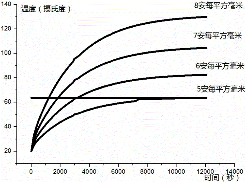
[0037] The experimental instruments include a linear motor, oscilloscope, driver, computer, multi-channel temperature tester, temperature sensor, etc. The experimental process is as follows: under the condition that the environmental conditions remain unchanged, the linear motor is driven by the driver to reciprocate, and the current density of the motor is tested by the oscilloscope during the operation process. The tester records the temperature values ​​of the motor at each set time from startup to stable temperature rise under different current densities.

[0038] The purpose of the experiment is to verify the rationality of the calculation of the parameters in the simulation solution, and t...


PUM


Abstract

The invention discloses a method for determining the working current and time of a permanent-magnet linear motor based on a taguchi method. The method comprises the following steps of: firstly, performing temperature rising and cooling tests of a test motor in the event that environmental conditions are constant; then, calculating steady temperature rising and cooling processes of the test motor under different current densities by using an electromagnetic-thermal coupling finite element calculation method, furthermore, comparing simulation and test results, if the simulation and test results are same, drawing out temperature rising and cooling curves of the motor, and if the simulation and test results are not same, modifying a simulation parameter according to an experimental result until the simulation and test results are same; and finally, determining temperature of the motor under different current densities, different operation times and different cooling times according to the determined temperature rising and cooling curves of the motor, and furthermore, obtaining temperature rising combinations most according with engineering practices of the selected motor under the current densities, the operation times and the cooling times by using a taguchi algorithm, such that an optimal combination is obtained.

Description

technical field [0001] The invention relates to a method for determining the selection of working current and working time when a permanent magnet linear motor under continuous duty is applied to periodic duty, which is part of linear motor design and motor utilization efficiency. Background technique [0002] With the continuous improvement of the requirements for motor miniaturization, high efficiency and energy saving, permanent magnet linear motors are widely used in CNC machine tools, launching systems and vertical and horizontal lifting systems due to their simple structure, high power density, high efficiency and accurate positioning. has been widely used. [0003] In order to save energy and improve efficiency, it is sometimes necessary to apply a motor running under continuous duty to short-term or periodic duty. According to the heating characteristics of the motor, select a motor running in continuous duty, so that the rated power of the motor is greater than the...

Claims


Application Information

Patent Timeline
Patent Type & Authority Applications(China)
IPC IPC(8): G06F17/50
CPCG06F30/23
Inventor 余海涛刘小梅黄磊胡敏强施振川封宁君夏涛徐鸣飞
Owner SOUTHEAST UNIV
Why Eureka
Try Eureka