

Electronic tag
A technology of electronic tags and microstrip lines, applied in the field of radio frequency identification, can solve the problems of low effective utilization of radiated energy, poor anti-interference, and inability to meet the requirements of road vehicles, and achieve the effect of improving the effective utilization
- Summary
- Abstract
- Description
- Claims
- Application Information
AI Technical Summary
Problems solved by technology
Method used
Image


Examples
Embodiment 1
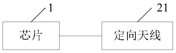
[0021] figure 2 A schematic structural diagram of an embodiment of an electronic tag provided by the present invention. Such as figure 2 As shown, the electronic tag in the embodiment of the present invention may specifically include a chip 1 and an antenna, and the antenna is a directional antenna 21 .
[0022] The directional antenna 21 is an antenna that transmits and receives microwaves particularly strongly in one or several specific directions, while transmitting and receiving microwaves in other directions is zero or extremely small. The chip 1 receives the microwave signal through the directional antenna 21 , and sends the electronic code stored in the chip 1 through the directional antenna 21 by virtue of the energy obtained by the induced current.
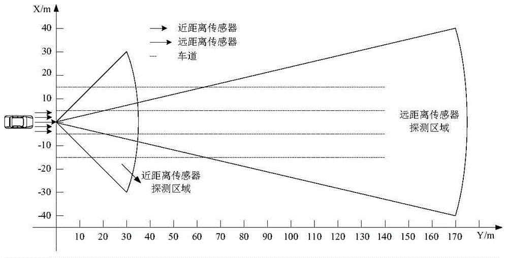
[0023] In the field of automatic driving, vehicle radar generally uses 77GHz ranging radar to determine the distance between the vehicle in front and the vehicle, such as image 3 As shown, the applicable range of th...
Embodiment 2
[0027] Figure 7 A schematic structural diagram of another embodiment of the electronic tag provided by the present invention. Such as Figure 7 As shown, the electronic tag of the embodiment of the present invention is figure 2 A possible implementation of the electronic tag of the shown embodiment, in figure 2 Technically in the illustrated embodiment, the directional antenna 21 may specifically be various antennas capable of directional transmission and reception of microwave signals, such as the array antenna 71 .
[0028] Further, in order to realize directional transmission and reception of microwave signals, the array antenna 71 may specifically include a microstrip line 72 and a plurality of parallel radiation units 73 ( Figure 7 Take four radiating units 73 as an example), and multiple radiating units 73 are respectively connected to the chip 1 through microstrip lines.
[0029] Further, the array antenna 71 may be specifically located on one side of the chip 1...
PUM
 Abstract
Description
Claims
Application Information