
Motor drying device and drying method

A drying device and motor technology, applied in the direction of electromechanical devices, manufacturing motor generators, electric components, etc., can solve the problems of motor insulation damage, lack of protection devices, excessive drying current, etc., to reduce drying costs and avoid more equipment , The effect of reducing the workload of personnel

Active Publication Date: 2016-08-10
CHINA FIRST METALLURGICAL GROUP
View PDF3 Cites 6 Cited by
  • Summary
  • Abstract
  • Description
  • Claims
  • Application Information

AI Technical Summary

Problems solved by technology

During the drying process, special personnel must measure the rotor temperature, coil insulation resistance, and absorption ratio every hour, and the drying power supply must be disconnected before each measurement. After the measurement, record the values ​​and draw the drying curve, which requires a lot of manpower. Disadvantages such as material resources
This kind of drying method is not only cumbersome to operate, but the simple electrical circuit also makes the excessive drying current lack the necessary protection device; and because the temperature of the motor rotor rises rapidly, if the power is not pulled off in time, the coil will be burnt out. In severe cases, the insulation of the motor is damaged and cannot be used
The exchange is carried out by artificially turning on and off the power, the operation process is very cumbersome and unsafe

Method used


Image

  • Motor drying device and drying method

Examples


Embodiment Construction

[0036] In order to make the object, technical solution and advantages of the present invention clearer, the present invention will be further described in detail below in conjunction with the accompanying drawings and embodiments. It should be understood that the specific embodiments described here are only used to explain the present invention, not to limit the present invention.

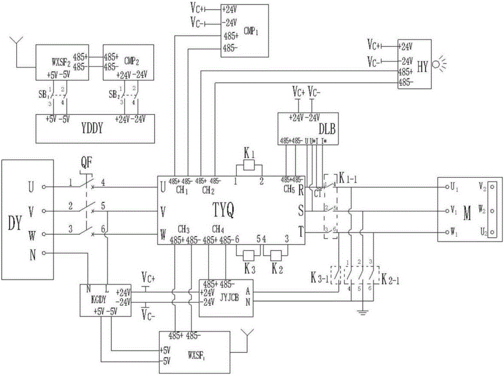
[0037] see figure 1, a motor drying device, including voltage regulation and transformation module TYQ, switching power supply KGDY, infrared temperature measurement module HY, insulation detection module JYJCB, first touch screen CMP 1 , power supply, first relay K 1 , the second relay K 2 and the third relay K 3 , the power supply is connected to terminals 1, 2, and 3 of the air switch QF through the U, V, and W terminals of the power input terminal DY, respectively, and the power supply is connected to the N terminal of the switching power supply KGDY through the N terminal of the power input...


PUM


Abstract

The invention discloses a motor drying device which comprises a voltage regulating and transformation module, an infrared temperature measurement module, an insulation detection module, a first touch screen, a power supply, a first relay, a second relay and a third relay, wherein the voltage regulating and transformation module is respectively connected with the infrared temperature measurement module, the insulation detection module, the touch screen, the power supply, the coil of the first relay, the coil of the second relay and the coil of the third relay, the voltage regulating and transformation module is connected with a motor through a current sensor and the normally-opened node of the first relay, the motor is connected with the insulation detection module through the normally-opened node of the second relay, the normally-opened node of the second relay is grounded, the motor is connected with the insulation detection module through the normally-opened node of the third relay, and the power supply is connected with the insulation detection module through a switch. The invention further provides a motor drying method. Drying of a motor can be done without repeatedly dismounting wires, the operation is simple and convenient, and the safety of an operator is ensured.

Description

technical field [0001] The invention relates to the field of motor drying, in particular to a motor drying device and a drying method. Background technique [0002] During the process of transportation, loading and unloading, storage and installation, the electrical characteristics of the motor are easily changed by factors such as the environment and climate. The more common situation is that the insulation resistance value of the motor does not meet the requirements. If the insulation is very low, it will be connected without drying. If the power supply is used, it is easy to cause an insulation breakdown accident. In order to ensure the safety, reliability and stability of the motor and protect the motor from burnout or breakdown due to insulation problems, the motor winding must be dried to restore its insulation strength to normal. The purpose of the motor drying treatment is to drive out the moisture in the windings and improve the insulation performance. The commonl...

Claims


Application Information

Patent Timeline
Patent Type & Authority Applications(China)
IPC IPC(8): H02K15/12
CPCH02K15/125
Inventor 李锐高宓何易寰梅俊李德家程青
Owner CHINA FIRST METALLURGICAL GROUP
Learn More