Permanent magnet suspension wing panel aeroelastic vibration generating set

A vibration power generation and aeroelasticity technology, applied in electromechanical devices, holding devices using magnetic attraction or thrust, wind power generation, etc. The effect of avoiding fatigue failure problems

Inactive Publication Date: 2016-08-10
NORTHWESTERN POLYTECHNICAL UNIV
View PDF5 Cites 8 Cited by
  • Summary
  • Abstract
  • Description
  • Claims
  • Application Information

AI Technical Summary

Problems solved by technology

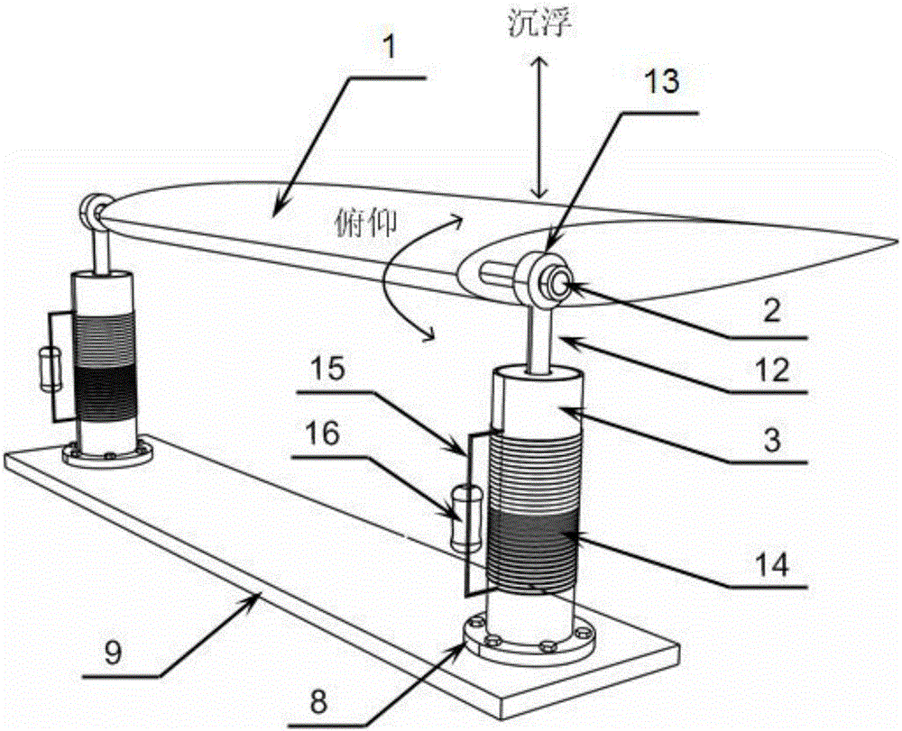
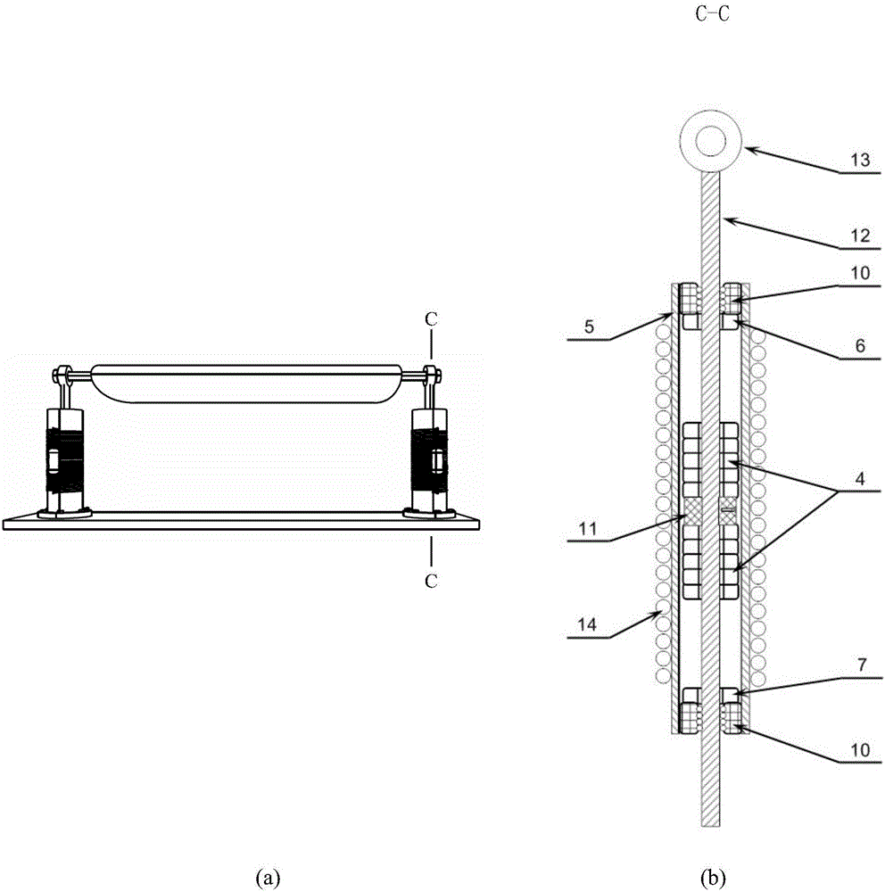
[0004] In order to solve the existing technology, the mechanical spring or cantilever beam element that provides the ups and downs stiffness of the wing section is prone to fatigue problems during the long-term vibration, especially the flutter power generation process, which seriously affects the service life and reliability of the aeroelastic vibration power generation device To solve the technical problem, the present invention proposes an aeroelastic vibration power generation device for a permanent maglev wing section, which includes two support forms: double support on both sides ( figure 1 ) and the middle single support type ( Figure 5 ), the wing section is supported by permanent magnetic suspension, and the energy conversion method of electromagnetic induction is used to generate electricity by using the aeroelastic vibration of the permanent magnetic suspension support wing section, which cancels the mechanical elastic support element in the design of the existing wing section aeroelastic vibration power generation device. Fatigue problems of wing support elements are virtually avoided

Method used


Image

  • Permanent magnet suspension wing panel aeroelastic vibration generating set
  • Permanent magnet suspension wing panel aeroelastic vibration generating set
  • Permanent magnet suspension wing panel aeroelastic vibration generating set

Examples


Embodiment Construction

[0038] Embodiments of the present invention are described in detail below, examples of which are shown in the drawings, wherein the same or similar reference numerals designate the same or similar elements or elements having the same or similar functions throughout. The embodiments described below by referring to the figures are exemplary and are intended to explain the present invention and should not be construed as limiting the present invention.

[0039] In describing the present invention, it should be understood that the terms "center", "longitudinal", "transverse", "length", "width", "thickness", "upper", "lower", "front", " Orientation indicated by rear, left, right, vertical, horizontal, top, bottom, inside, outside, clockwise, counterclockwise, etc. The positional relationship is based on the orientation or positional relationship shown in the drawings, which is only for the convenience of describing the present invention and simplifying the description, rather than ...


PUM


Abstract

The invention provides a permanent magnet suspension wing panel aeroelastic vibration generating set. The permanent magnet suspension wing panel aeroelastic vibration generating set comprises two support forms, namely, a double-side double support form and a middle single support form, a wing panel is supported by permanent magnet suspension; and an electromagnetic induction energy transformation type is adopted. Power is generated by means of aeroelastic vibration of a permanent magnet suspension support wing panel, and a mechanical elastic support element in a conventional wing panel aeroelastic vibration generating set design is removed, so that the problem of fatigue of a wing panel support element is solved fundamentally. A linear bearing is taken as a guide device for a support rod to perform ups and downs in conjunction with the wing panel, and a suspension annular permanent magnet is fixedly connected to the support rod, so that surface contact between the suspension annular permanent magnet and a cylindrical sleeve is avoided, and friction force of permanent magnet suspension support is lowered. The permanent magnet suspension support has a nonlinear rigidity feature, and the non-linear rigidity feature of the suspension annular permanent magnet can be changed by adjusting a distance between fixed annular permanent magnets at two ends of the cylindrical sleeve, so that the wing panel can perform chattering motion at a relatively low wind speed.

Description

technical field [0001] The invention relates to the field of wind-induced vibration energy collection, in particular to an aeroelastic vibration power generation device for a permanent magnetic levitation wing section, which converts wind energy into electric energy by using permanent magnetic levitation, aeroelastic vibration phenomenon and electromagnetic induction principle. Background technique [0002] The existing aeroelastic vibration energy harvesting technology mainly relies on the aeroelastic vibration phenomenon of the elastically supported wing section in the airflow, including flutter, vortex induced vibration, galloping, etc., first converts wind energy into mechanical vibration energy, and then converts it through piezoelectric energy Or the electromagnetic induction method converts mechanical vibration energy into electrical energy to achieve the purpose of power generation. In the existing aeroelastic vibration energy harvesting technology, mechanical spring...

Claims


Application Information

Patent Timeline
Patent Type & Authority Applications(China)
IPC IPC(8): H02K35/02H02N15/00F03D80/00
CPCH02K35/02H02N15/00Y02E10/72
Inventor 谷迎松杨智春贺顺陈兆林
Owner NORTHWESTERN POLYTECHNICAL UNIV
Why Eureka
Try Eureka