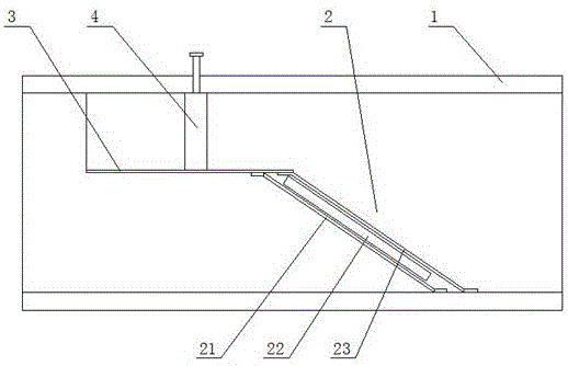
Pipeline filter
A pipeline filter and filter technology, applied in the filter field, can solve problems such as damage, achieve the effect of preventing rupture, preventing excessive pressure, and ensuring smooth flow
- Summary
- Abstract
- Description
- Claims
- Application Information
AI Technical Summary
Problems solved by technology
Method used
Image
Examples
Embodiment 1
[0038] Such as figure 1 As shown, a pipeline filter 2 of the present invention discloses a pipeline filter 2, which includes a pipe body 1, and a separation plate 3 is arranged in the pipe body 1, and the separation plate 3 separates the pipe body 1 The channel is divided into a pressure relief channel and a filter channel, and a filter 2 is arranged on the filter channel. A valve body 4 is arranged on the pressure relief passage. The valve body 4 is used to control the flow of the pressure relief passage to ensure the effective filtration of the filter 2 , and the valve body 4 can also control and adjust the pressure difference on both sides of the filter 2 . The flow passer is sheet-shaped, and the filter 2 is obliquely arranged at the entrance of the filter channel, and the filter 2 and the axial direction of the pipeline form an included angle of 30-60 degrees. After the filter 2 is tilted, it plays the role of drainage to ensure that the pressure on the filter 2 is redu...
Embodiment 2
[0043] The intelligent control system of the pipeline filter includes a pipeline unit, a filter unit, a valve unit, a partition unit, a detection unit and a control unit;
[0044] The pipe unit includes a pipe body, an annular spoiler layer arranged on the inner wall of the pipe, and a reinforcement layer fixed on the outer wall of the pipe; the spoiler layer is composed of a plurality of spoiler rings, and the distance between adjacent spoiler rings is 2-3cm, the height of the spoiler ring protruding from the pipe body is 4-6mm; the pipe body is a polyethylene plastic pipe; the reinforcement layer is a ring-shaped structure made of carbon steel material, between the reinforcement layer and the pipe body There is a 0.2-0.5mm thick flax braid layer between them;
[0045] The partition unit includes an isolation plate and a position regulator, the regulator includes an adjustment frame, a screw, and a partition motor, the isolation plate is installed on the adjustment frame, the...
Embodiment 3
[0052] Based on embodiment 2 intelligent control system, its control method is:
[0053] Step 1: When the isolation plate is set at a certain position in the pipe body, the cross-sectional ratio of the pressure relief channel to the filter channel is (1-1.5): (1.5-1.8);
[0054] Step 2: Pass the water flow with a water pressure of 100-150kPa into the pipeline unit, and measure the water pressure at the inlet of the pipeline unit through the third pressure sensor;
[0055] Step 3: The controller controls the rotation of the valve motor to control the action of the valve unit, and measures the water pressure in the pressure relief channel through the first pressure sensor; measures the water pressure in the filter channel through the second sensor;
[0056] Step 4: The controller controls the valve motor so that the water pressure at the inlet of the pipeline unit: the water pressure in the filter channel is not greater than 1.35;
[0057] Step 5: When the valve motor is fully ...
PUM
| Property | Measurement | Unit |
|---|---|---|
| thickness | aaaaa | aaaaa |
Abstract
Description
Claims
Application Information
 - R&D
- Intellectual Property
- Life Sciences
- Materials
- Tech Scout
- Unparalleled Data Quality
- Higher Quality Content
- 60% Fewer Hallucinations
Browse by: Latest US Patents, China's latest patents, Technical Efficacy Thesaurus, Application Domain, Technology Topic, Popular Technical Reports.
© 2025 PatSnap. All rights reserved.Legal|Privacy policy|Modern Slavery Act Transparency Statement|Sitemap|About US| Contact US: help@patsnap.com

