Electrically conductive filter bag and production method thereof

A manufacturing method and filter bag technology, applied in separation methods, chemical instruments and methods, and dispersed particle filtration, etc., can solve problems such as failure, poor conductivity, and poor contact of keels, and achieve the effect of preventing breakage

Active Publication Date: 2016-08-17
山东兴国新力环保科技股份有限公司
View PDF5 Cites 8 Cited by
  • Summary
  • Abstract
  • Description
  • Claims
  • Application Information

AI Technical Summary

Problems solved by technology

The price of this kind of filter bag is quite expensive, and the stainless steel fiber or carbon fiber will be unevenly distributed in the surface layer during production, resulting in poor contact with the keel, resulting in poor conductivity and prone to problems; the other is in the filter bag Conductive yarn is added to the base fabric to conduct static electricity away during use. The conductivity of this filter bag is worse than that of carbon fiber or stainless steel fiber in the surface layer.
[0003] Although there is a design of embedding a conductive strip in the bag body in the existing conductive filter bag, the conductive effect is not ideal in actual use, and the conductive strip is easily broken and causes conductive failure
Most of the existing sewing methods use to sew the filter bag first, and then sew the conductive tape on the filter bag. First, this method needs to be sewn twice and the sewing speed is relatively slow; secondly, the method is to sew the conductive tape in the second step. It is necessary to sew on the filter bag base material that has been sewn into a tubular shape. Since the filter bag base material is tubular, it is inconvenient for the existing sewing equipment to sew the conductive tape on the outer wall or the inner wall of the filter bag base material.

Method used


Image

  • Electrically conductive filter bag and production method thereof
  • Electrically conductive filter bag and production method thereof
  • Electrically conductive filter bag and production method thereof

Examples


Embodiment 1

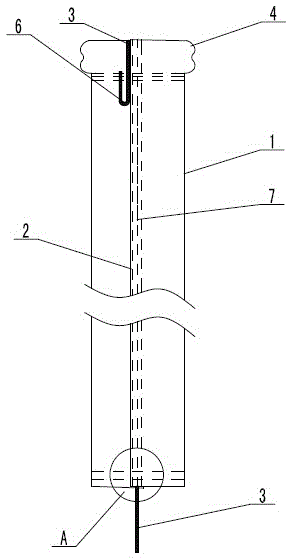
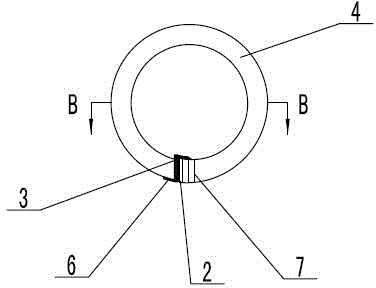
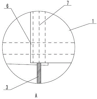
[0033] Refer to attached Figure 1~4 : A conductive filter bag, comprising a bag body 1 and a bag bottom sewn on the bottom of the bag body 1, a double-layer lap 2 for sewing is distributed on the bag body 1, and a conductive filter is arranged inside the double-layer lap 2. The belt 3 and the conductive belt 3 are fixed by the suture 7 sewn on the double-layer lap; the upper opening of the bag body 1 is provided with an annular skeleton, the annular skeleton includes an elastic ring 5, and the upper edge of the bag body 1 is folded inward and fixed to form a flip The edge 4 and the elastic ring 5 are arranged in the flange 4 . The top of the conductive strip 3 is exposed from the top of the double-layer lap 2, and is wound from the inside of the bag body 1 to the outside of the bag body 1, and then fixed on the bag body 1 below the annular frame; exposed and placed outside the bag body 1 . The conductive strip 3 is sewn and fixed on the bag body 1 below the elastic ring 5 ....

Embodiment 2

[0040] The structure of the conductive filter bag of this embodiment is the same as that of Embodiment 1, except that the bottom end of the conductive strip 3 is 150 mm long from the bottom of the double-layer lap, and the top of the conductive strip 3 is 200 mm long from the top of the double-layer lap 2. The width of the conductive strip 3 is 3mm, and the conductive strip 3 is made of bare copper flat wire. The double-layer lap 2 is formed by lapping the side walls of the upper and lower layers of the bag body 1, and the width of the double-layer lap 2 is 15mm.

[0041] The bottom of the bag 8 is circular, and the circumference of the circle of the bottom of the bag 8 is sewn and fixed with the edge of the bottom of the bag body 1, or two parallel sutures can be used to sew and fix the bottom of the bag body 1 to form the bottom of the bag 8.

[0042] The manufacturing method of this embodiment includes the following steps:

[0043] a) Conductive belt 3 and bag body 1 blank...

Embodiment 3

[0048] The structure of the conductive filter bag of this embodiment is the same as that of Embodiment 1, except that the bottom end of the conductive strip 3 exposes a length of 100 mm from the bottom end of the double-layer lap, and the top of the conductive strip 3 exposes a length of 150 mm from the top of the double-layer lap 2. The width of the conductive strip 3 is 4mm, and the conductive strip 3 is made of bare copper flat wire. The double-layer lap 2 is formed by overlapping the side walls of the upper and lower layers of the bag body 1, and the width of the double-layer lap 2 is 18 mm.

[0049] The bottom 8 of the bag is circular, and the circumference of the circle of the bottom 8 is sewn and fixed to the bottom edge of the bag body 1 . Alternatively, two parallel sutures 7 can be used to sew and fix the bottom end of the bag body 1 to form the bottom 8 of the bag.

[0050] The manufacturing method of this embodiment includes the following steps:

[0051] a) Conduc...


PUM

PropertyMeasurementUnit
lengthaaaaaaaaaa
lengthaaaaaaaaaa
widthaaaaaaaaaa

Abstract

An electrically conductive filter bag and a production method thereof belong to the technical field of electrically conductive bag. The electrically conductive filter bag includes a bag body (1) and q bag bottom sewn at the bottom of the bag body (1); the bag body (1) is provided with a double-layer edge for sewing (2); the double-layer edge (2) is internally provided with a conductive strip (3); the conductive strip (3) is fixed by suture (7) sewn on the double-layer edge; the upper end of the bag body (1) is provided with an annular skeleton; the top of the conductive strip (3) exposes from the top of the double-layer edge (2), and winds from the inside of the bag body (1) to the outside of the bag body (1), and is then fixed below the annular skeleton onto the bag body (1); and the bottom end of the conductive strip (3) exposes from the bottom of the double-layer edge and is placed outside the bag body (1). The electrically conductive filter bag has good conductive effect, prevents conductive failure caused by collision of the keel and the conductive strip in the bag body. The production method completes sewing of the bag body and the conductive strip in one step, and improves the production efficiency of the electrically conductive filter bag.

Description

technical field [0001] A conductive filter bag and a manufacturing method thereof belong to the technical field of conductive filter bags. Background technique [0002] The use of non-conductive filter bags in dust removal conditions with high dust concentration and static electricity can easily cause dust explosions, damage filter bags and other dust collector accessories, and even cause greater safety accidents. In the existing technology, there are two main methods to solve the problem of static electricity in the dust. One is to add stainless steel fiber and carbon fiber to the surface layer of the felt when making the filter bag, and pass through the stainless steel fiber contained in the surface layer during use. Fibers or carbon fibers conduct static electricity away. The price of this kind of filter bag is quite expensive, and the stainless steel fiber or carbon fiber will be unevenly distributed in the surface layer during production, resulting in poor contact with...

Claims


Application Information

Patent Timeline
Patent Type & Authority Applications(China)
IPC IPC(8): B01D46/02B01D46/50
Inventor 王玉华齐贵山蒋树军
Owner 山东兴国新力环保科技股份有限公司
Why Eureka
Try Eureka