Cloth thickness detection device of sewing machine

A thickness detection and sewing machine technology, applied in the field of sewing, can solve the problems of high installation requirements, complex structure, large detection errors, etc., and achieve the effects of high detection accuracy, high detection accuracy and wide application range.

Active Publication Date: 2016-08-17
ZHEJIANG ZOBOW MECHANICAL & ELECTRICAL TECH
View PDF11 Cites 21 Cited by
  • Summary
  • Abstract
  • Description
  • Claims
  • Application Information

AI Technical Summary

Problems solved by technology

This solution is to detect the thickness of the fabric through mechanical measurement. Although it can detect the thickness of different fabrics, there are still some problems: this purely mechanical measurement method has low thickness detection efficiency, troublesome operation, and troublesome detection methods.
For example, the infrared sensor detection technology mainly includes two types of infrared direct radiation and reflective type. These two methods have high requirements for the use environment, and are easily affected by external light (sunlight) to cause false detection or failure, and for Hollow, mesh fabrics or fabrics with high transparency, the detection will fail
In addition, due to the limited installation method of

Method used


Image

  • Cloth thickness detection device of sewing machine
  • Cloth thickness detection device of sewing machine
  • Cloth thickness detection device of sewing machine

Examples


Embodiment 1

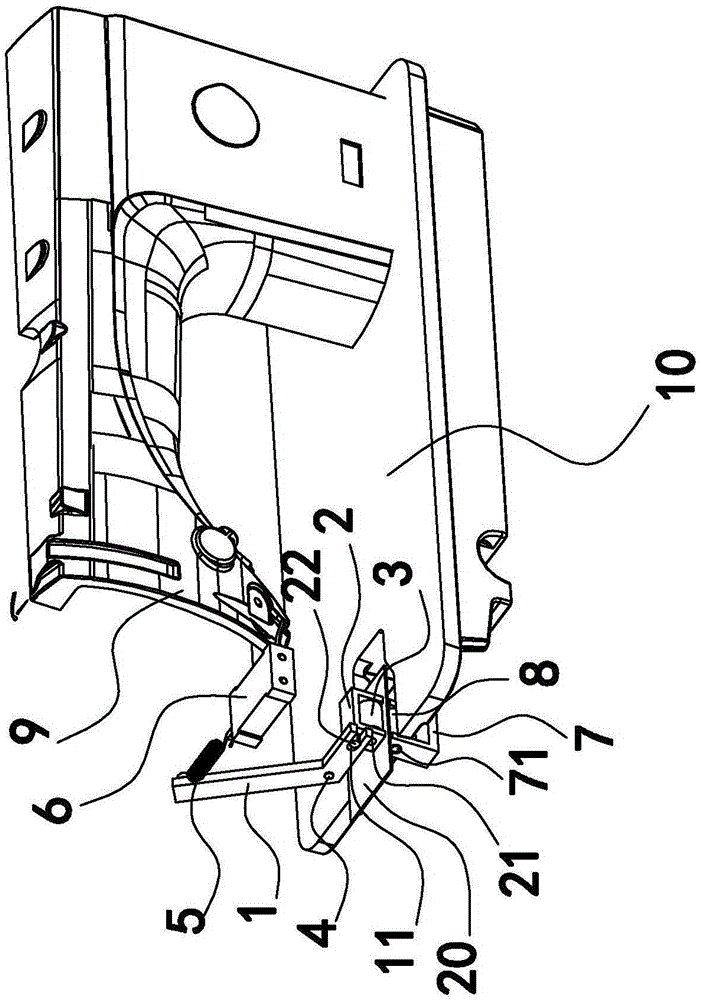
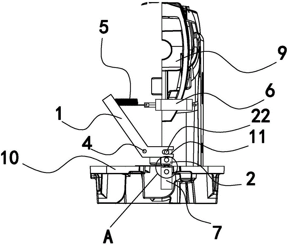
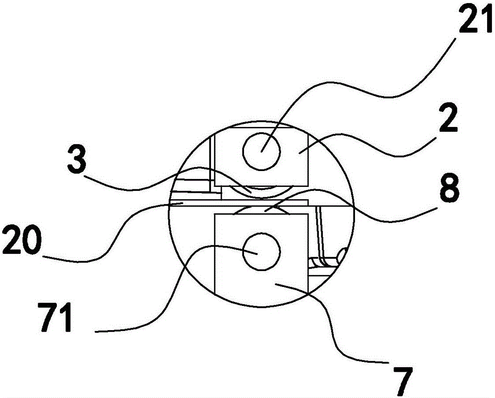
[0023] Such as figure 1 , 2 As shown in and 3, the sewing machine cloth thickness detection device includes a rotating arm 1, a sensor device and an upper pressing wheel mounting seat 2, and an upper pressing wheel 3 is installed on the upper pressing wheel mounting seat 2, and the upper pressing wheel 3 rotates through the rotating shaft-21 Be installed on the upper pressure roller mounting seat 2 and the lower end surface protrudes outside the upper pressure roller mounting seat 2 lower end surface, the middle part of the rotating arm 1 is installed on the sewing machine head 9 by the pin shaft 4 and the rotating arm 1 swings around the pin shaft 4 . The lower end of the swivel arm 1 is provided with a bar-shaped groove 11, and the upper pressing wheel mounting seat 2 is fixedly connected with a transmission shaft 22. The transmission shaft 22 is installed in the bar-shaped groove 11 and can move back and forth therein. The groove width of the bar-shaped groove 11 is It is ...

Embodiment 2

[0033] The structure difference between the present embodiment and the first embodiment is that the sensor device of the present embodiment is an angle sensor, and the angle sensor is fixedly installed on the head of the sewing machine and directly connected with the upper end of the rotating arm. Other structures are the same as those in Embodiment 1, and will not be repeated here. The difference between this embodiment and the method principle of Embodiment 1 is that the angle sensor in this embodiment directly detects the rotation angle of the rotating arm, and then detects the height of the upper pressure roller mounting seat by detecting the rotation angle, which is The measured fabric thickness. Other methods and principles are the same as those in Embodiment 1, and will not be repeated here.

Embodiment 3

[0035] The difference between the structure of this embodiment and the first embodiment is that this embodiment cancels the structure of the lower pressure roller, the lower pressure roller mounting seat, the second rotating shaft and the opening on the needle plate in the first embodiment. The wheel is directly located on the needle plate of the sewing machine table, and the lower end surface of the upper pressing wheel is directly connected with the needle plate. Other structures are the same as those in Embodiment 1, and will not be repeated here.

[0036] The difference between this embodiment and the method and principle of Embodiment 1 is that when the cloth enters the detection device through the gap between the lower end surface of the upper pressure roller and the needle plate, since the upper pressure roller can wrap around the upper pressure roller mounting seat 2 The upper rotating shaft-21 rotates, and when the cloth enters, the upper pinch wheel will rotate with ...


PUM


Abstract

The invention provides a cloth thickness detection device of a sewing machine, belongs to the technical field of sewing, and solves the problems of high requirements on installation environment and poor detection accuracy by a traditional cloth thickness detection device. The cloth thickness detection device of the sewing machine comprises a rotary arm, a sensor device and an upper pinch roller installation seat, wherein the upper pinch roller installation seat is provided with an upper pinch roller; the upper pinch roller is rotatably installed on the upper pinch roller installation seat through a first rotation shaft, the lower end surface of the upper pinch roller extends out of the lower end surface of the upper pinch roller installation seat; the middle of the rotary arm is installed on the head of the sewing machine through a hinge pin, and the rotary arm swings around the hinge pin; the upper pinch roller installation seat is connected with the lower end of the rotary arm through a transmission structure; the transmission structure can drive the rotary arm to swing around the hinge pin; the sensor device is connected with the upper end of the rotary arm, can detect the information of the amplitude of swing of the rotary arm and sends the information of the amplitude of swing to a sewing machine electronic controller. The cloth thickness detection device of the sewing machine has the advantages of simple structure, convenience in installation and high detection accuracy.

Description

technical field [0001] The invention belongs to the technical field of sewing, and relates to a sewing machine cloth thickness detection device. Background technique [0002] The presser foot mechanism in existing sewing machines is generally able to adapt to different thicknesses of sewing materials, but when sewing different thicknesses of fabrics, the controller cannot intelligently adjust the speed and torque according to the different thicknesses of the sewing materials to ensure smooth sewing . In order to solve this problem, the technical solution disclosed by the Chinese patent whose notification number is CN205066638U, which is convenient for detecting the thickness of the cloth, includes a base plate, a support column, a support box and a measuring rod; the measuring rod includes an outer rod, an inner rod and a first spring, and the inner rod From top to bottom, it includes a contact section, a limit section and an extension section that are coaxial with each oth...

Claims


Application Information

Patent Timeline
IPC IPC(8): D05B29/02G01B21/08
CPCD05B29/02G01B21/08
Inventor 王红光双慧
Owner ZHEJIANG ZOBOW MECHANICAL & ELECTRICAL TECH
Why Eureka
Try Eureka