
Prefabricated assembly well wall structure and construction method thereof

A prefabricated assembly and well wall technology, which is applied in the configuration of water supply devices, drainage structures, and water supply pools, etc., can solve the problems of long exposure time of foundation pit walls, complicated wet operation procedures, and difficulty in quality assurance, and it is easy to achieve engineering quality. Control and solve the effect of water supply and slurry supply and mud discharge for multiple equipments, and the cost is low

Active Publication Date: 2016-08-17
SHANGHAI MECHANIZED CONSTR GRP
View PDF14 Cites 6 Cited by
  • Summary
  • Abstract
  • Description
  • Claims
  • Application Information

AI Technical Summary

Problems solved by technology

At present, many large cities in my country, such as Shanghai and Beijing, have the problem of weak water storage capacity. Therefore, it is urgent to establish deep underground water storage projects, especially the development of underground shaft projects. The construction of the cast-in-place shaft wall structure not only has a long construction period, complicated wet operation procedures, and a long exposure time of the groove wall of the foundation pit, but also the quality is difficult to guarantee, which fails to meet the actual needs

Method used


Image

  • Prefabricated assembly well wall structure and construction method thereof
  • Prefabricated assembly well wall structure and construction method thereof
  • Prefabricated assembly well wall structure and construction method thereof

Examples


Embodiment Construction

[0033] The present invention is described in detail below in conjunction with accompanying drawing:

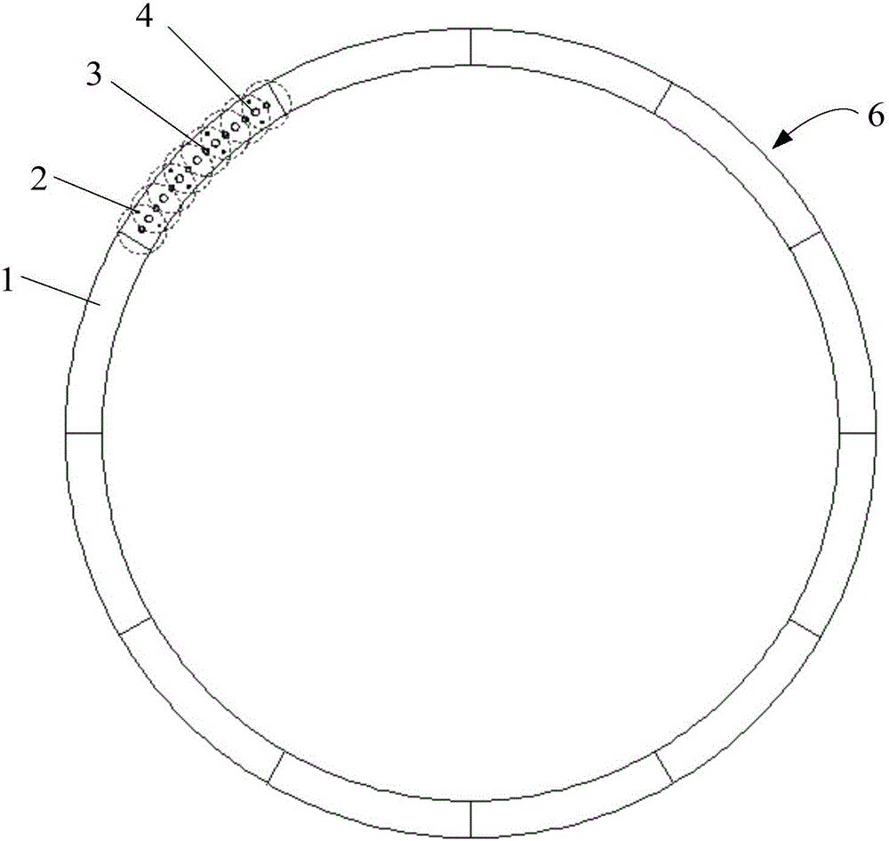
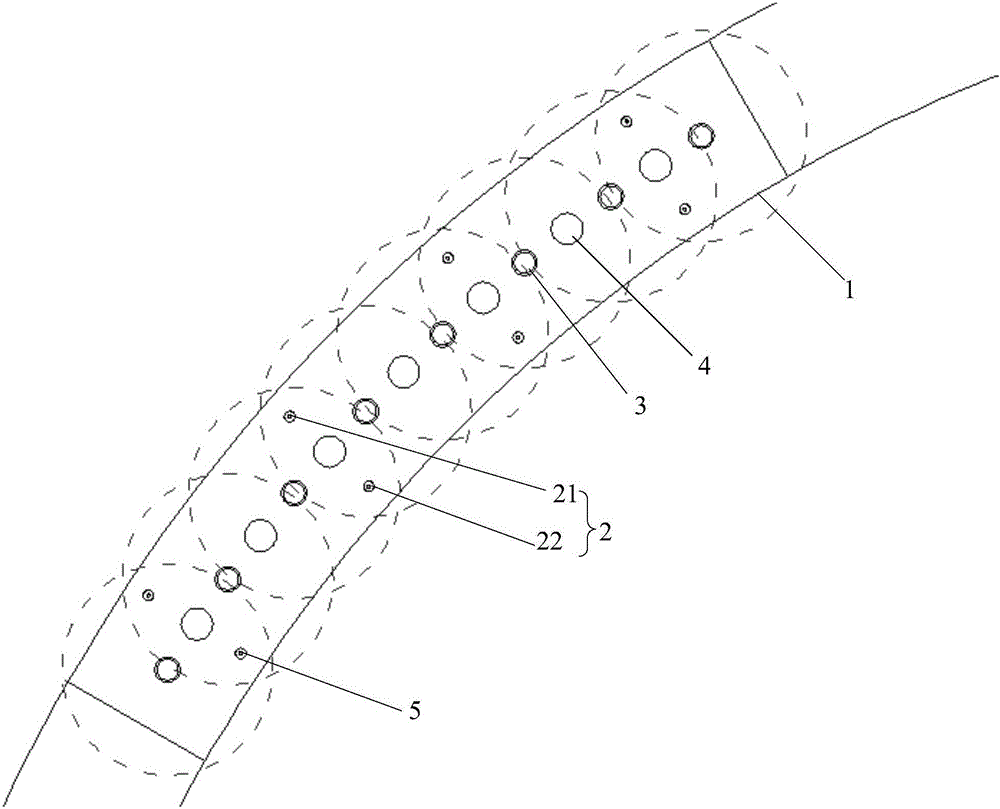
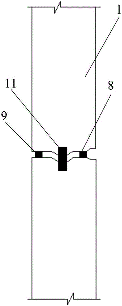
[0034] Such as Figure 1-5 As shown, the present invention provides a prefabricated well wall structure, which is assembled by splicing and assembling a number of prefabricated segments 1 along the longitudinal and circumferential directions. The prefabricated segments 1 are provided with a number of prestressed through holes 2 running through the upper and lower ends at intervals. , a number of grouting holes 3 and a number of grouting holes 4, the prestressed through hole 2 is provided with a prestressed connector 5, the prestressed connector 5 stretches out from the upper and lower ends of the prestressed through hole 2 , both circumferential ends of the inner side of the prefabricated segment 1 are provided with oblique inner holes, and oblique connecting sleeves 10 or oblique bolts 12 are pre-embedded in the oblique inner holes, and the outer diameter of the oblique bolts...


PUM


Abstract

The invention discloses a prefabricated assembly well wall structure and a construction method thereof. The prefabricated assembly well wall structure is formed by splicing and assembling a plurality of prefabricated pipe pieces in the longitudinal direction and the annular direction; a plurality of prestress through holes penetrating through the upper end and the lower end, a plurality of grouting holes and a plurality of slurry discharging holes are formed in each prefabricated pipe piece at intervals; a prestress connecting element is arranged in each prestress through hole, and extends out from the upper end and the lower end of the corresponding prestress through hole; inclined inner holes are formed in two ends of the annular direction of the inner side of each prefabricated pipe piece; an inclined connecting sleeve is embedded in each inclined inner hole; and a force transmission bushing and a water stop structure are arranged between two prefabricated pipe pieces which are adjacent in the longitudinal direction and the annular direction. The prefabricated assembly well wall structure is formed by splicing the prefabricated pipe pieces; the vertical shaft foundation pit excavation enclosure exposure time is reduced; the complicated process of a wet construction work procedure is simplified; the work intensity of workers is reduced; the construction speed is high; the cost and the manufacturing price are low; the environment pollution is low; and good social effects and economic effects are achieved.

Description

technical field [0001] The invention relates to the technical field of underground building construction, in particular to a prefabricated well wall structure and a construction method thereof. Background technique [0002] With the acceleration of the urbanization process, the urban population is highly dense, and the production and transportation are dense, which makes the contradiction of parking difficult in large and medium-sized cities such as Beijing, Shanghai, and Guangzhou increasingly prominent. Underground parking garages are a hot topic worthy of research. At present, various countries are trying their best to promote "sponge" cities, and have conducted a series of explorations on how to improve the water storage function of super-large cities. Among them, Tokyo, Japan has established the world's largest deep storage. The water pipeline project has effectively improved the water storage function of the city. At present, many large cities in my country, such as S...

Claims


Application Information

Patent Timeline
IPC IPC(8): E03B11/14E03F5/10
CPCE03B11/14E03F5/10
Inventor 吴欣之严时汾李操周铮周蓉峰
Owner SHANGHAI MECHANIZED CONSTR GRP
Learn More