
Safety lock for automatic teller machine

An automatic teller machine and safety lock technology, applied in the field of safety locks, can solve the problems of low safety factor, easy to be pryed open, difficult to prevent lawbreakers, etc., and achieve the effect of ingenious structure and preventing the motor from stalling and burning out.

Active Publication Date: 2016-08-17
江苏华册物联网科技有限公司
View PDF5 Cites 2 Cited by
  • Summary
  • Abstract
  • Description
  • Claims
  • Application Information

AI Technical Summary

Problems solved by technology

[0003] Existing safety locks are either complex in structure and high in cost, or simple in structure with low safety factor and easy to be pried open, and safety locks generally have keyholes, which are mechanical unlocking methods, and it is difficult to prevent criminals from

Method used


Image

  • Safety lock for automatic teller machine
  • Safety lock for automatic teller machine
  • Safety lock for automatic teller machine

Examples


Embodiment Construction

[0020] The present invention will be further described below in conjunction with the accompanying drawings.

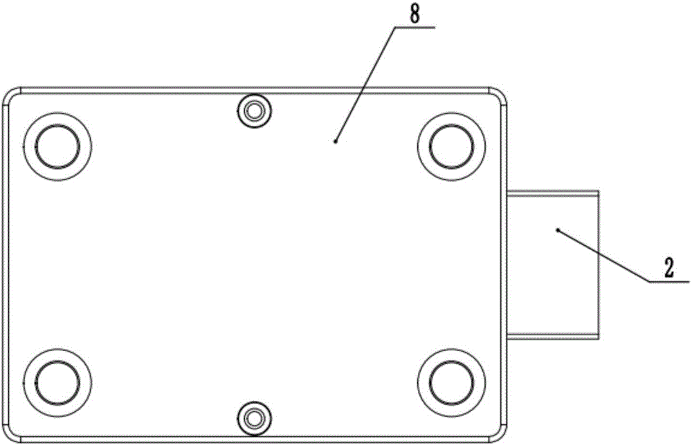
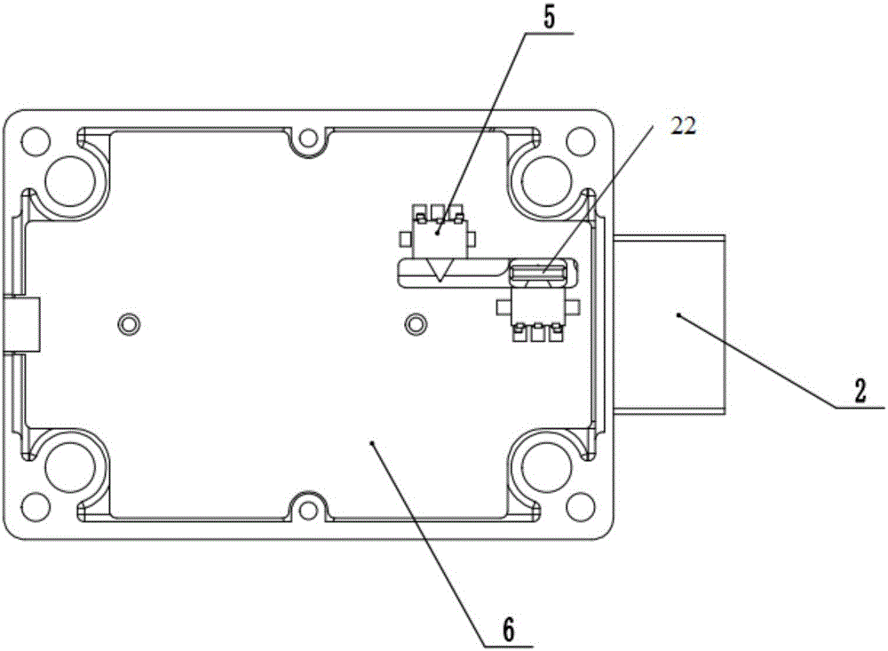
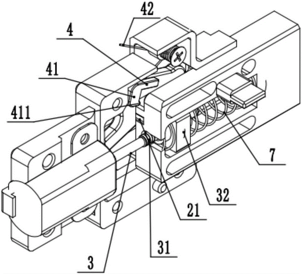
[0021] as attached figure 1 to attach Figure 5 The safety lock for the automatic teller machine shown includes a mounting base 1, a dead bolt 2, a dead bolt driving assembly 3 and a dead bolt anti-prying assembly 4; Driven by the deadbolt drive assembly 3 , it expands and contracts back and forth relative to the mounting base 1 ; after the deadbolt 2 is stretched out in place, the deadbolt anti-tampering component 4 blocks the deadbolt 2 .

[0022] The deadbolt drive assembly 3 includes a motor 31, a screw 32 and a screw nut 33, the screw 32 is arranged on the output shaft of the motor 31, and the screw nut 33 is arranged on the deadbolt 2 Above, the screw rod 32 cooperates with the screw nut 33 to form a screw nut pair. There is a cavity on the dead bolt 2, and the screw nut 33 is in a sliding fit with the cavity, and the screw nut 33 is provided with springs 7 at...


PUM


Abstract

The invention discloses a safety lock for an automatic teller machine. The safety lock comprises an installation base, a spring bolt, a spring bolt drive assembly and a spring bolt prying-preventing assembly; the spring bolt is connected in a sliding mode relative to the installation base and can be stretched back and forth relative to the installation base under the driving effect of the spring bolt drive assembly; after the spring bolt stretches out in place, the spring bolt prying-preventing assembly can clamp the spring bolt. According to the safety lock for the automatic teller machine, physical lock holes do not exist, and a drive motor rotates forwards and reversely for driving the spring bolt to stretch out and draw back; the prying-preventing assembly is arranged and can clamp the spring bolt when the spring bolt stretches out, and the lock can be protected against prying; a screw rod and a screw rod nut of the spring bolt drive assembly can be separated after the spring bolt reaches the extreme position, the phenomenon that the motor is locked and burned out because a control system breaks down can be prevented, and the service life of the safety lock can be prolonged.

Description

technical field [0001] The invention relates to the field of safety locks, in particular to a safety lock for automatic teller machines. Background technique [0002] Automatic teller machine, or ATM, refers to a small machine set up by a bank in different locations, using a tape on a credit card-sized plastic card to record the customer's basic account information (usually a bank card), so that the customer can use the machine. Bank counter services such as withdrawals, deposits, transfers, etc. Most customers call this self-service machine an automatic teller machine. Protecting the money in the ATM from being stolen can protect the property safety of the country and the people, so the security of the lock of the ATM is extremely important. [0003] Existing safety locks either have a complex structure and high cost, or have a simple structure with a low safety factor and are easy to be picked open, and the safety lock generally has a keyhole, which is a mechanical unlock...

Claims


Application Information

Patent Timeline
IPC IPC(8): E05B65/00E05B17/20E05B47/00E05B15/00
CPCE05B15/00E05B17/2019E05B17/2034E05B47/0012E05B65/00E05B2047/0018E05B2047/0069
Inventor 李瑞峰王威
Owner 江苏华册物联网科技有限公司
Learn More