Sandstone machine

A sandstone and component technology, applied in the field of stone mining equipment, can solve the problems affecting the operation efficiency, precision, complex structure and high performance requirements of horizontal moving lifting, and achieve stable and reliable longitudinal cutting and transverse cutting, simple structure and reasonable design. Effect

Active Publication Date: 2016-08-17
QUANZHOU HAIENDE ELECTROMECHANICAL TECH DEV
View PDF4 Cites 1 Cited by
  • Summary
  • Abstract
  • Description
  • Claims
  • Application Information

AI Technical Summary

Problems solved by technology

Therefore, since the slitting saw machine components and the cross-cut saw machine components each need to complete multi-dimensional actions, all current stone mining equipment, slitting saw machine components and cross-cut saw machine components are designed independently of each other, especially the longitudinal The saw blade and the cross saw blade must each be equipped with a set of rotary drive mechanisms, which is complex in structure and cumbersome to operate
Furthermore, regardless of the slitting saw machine component or the cross-cut saw machine component, the multi-dimensional action design adopts the integrated design of the rotary drive mechanism and the saw blade, that is, during the horizontal movement or lifting operation of the saw blade, the rotary drive mechanism follows Synchronous action, on the one hand, has higher requirements on the performance of related mechanisms for horizontal movement and lifting operations, and on the other hand, it will also affect the efficiency and accuracy of horizontal movement or lifting operations, and even affect the operating performance of the whole machine

Method used


Image

  • Sandstone machine
  • Sandstone machine
  • Sandstone machine

Examples


Embodiment Construction

[0091] The present case will be described in further detail below in conjunction with the accompanying drawings and specific embodiments.

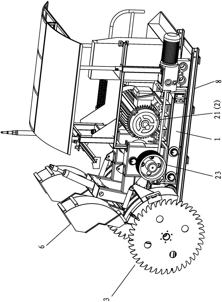
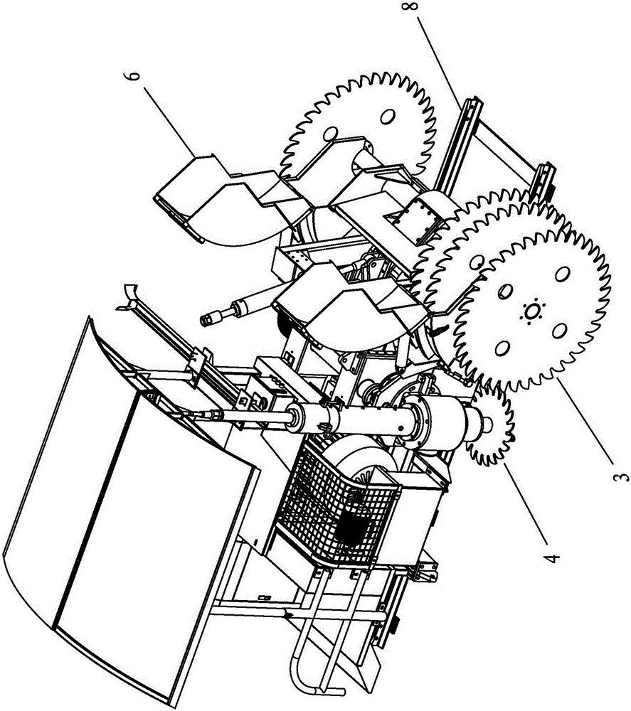
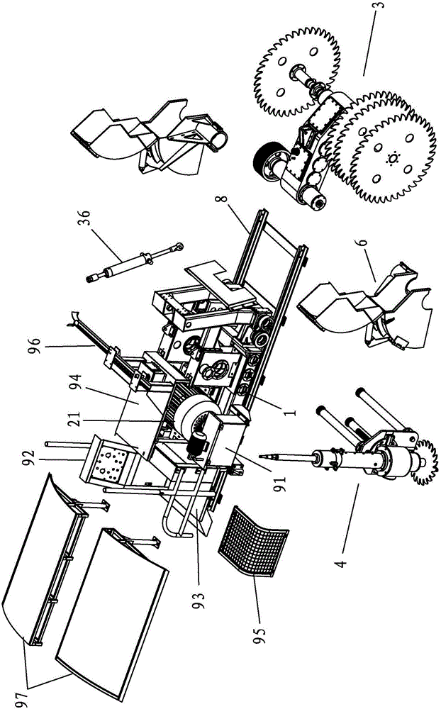
[0092] This case involves a sandstone machine, such as Figure 1-5 As shown, it mainly includes a trolley 1, and a total drive assembly 2, a slitting assembly 3 and a cross-cutting assembly 4 arranged on the trolley 1.

[0093] The total drive assembly 2 mainly includes a power source 21 and an input shaft 22 which are in transmission connection with each other. One embodiment of the transmission connection is a belt transmission method. The input shaft 22 is provided with a large pulley 23, and the output shaft of the power source 21 is connected to the large pulley 23 through a belt (not shown). The trolley 1 is provided with an underframe 11, the underframe 11 is provided with a motor base, and the power source 21 is fixedly installed on the motor base. The base frame 11 is provided with two left and right swing arm supports 12 side b...


PUM


Abstract

The invention discloses a sandstone machine. The sandstone machine comprises a walking vehicle, and a general driving assembly, a longitudinal cutting assembly and a transverse cutting assembly which are arranged on the walking vehicle, wherein the general driving assembly comprises a power source and an input shaft which are in mutual transmission connection; the longitudinal cutting assembly comprises a transmission gear assembly, a front main shaft and a longitudinal cutting saw blade; the transmission gear assembly is in transmission connection between the input shaft and the front main shaft; the longitudinal cutting saw blade is mounted on the front main shaft; the transverse cutting assembly comprises a bevel gear set, a side main shaft and a transverse cutting saw blade; the bevel gear set is in transmission connection between the input shaft and the side main shaft; and the transverse cutting saw blade is mounted on the side main shaft. The longitudinal cutting assembly and the transverse cutting assembly are ingeniously combined and designed, and share one set of the general driving assembly, so that the whole machine has a simple structure and a reasonable design and is simple and convenient to manipulate; and the general driving assembly is fixedly and externally mounted, and the movement design of other dimensions of the longitudinal cutting assembly and the transverse cutting assembly can ingeniously avoid the general driving assembly and an independent design is carried out, so that the sandstone machine has the advantages of stability and reliability and high efficiency on longitudinal cutting and transverse cutting.

Description

technical field [0001] The invention relates to a stone mining equipment, in particular to a sandstone machine. Background technique [0002] Stone mining equipment is a mechanized equipment that divides mine stones into blocks and transports them out. Existing stone mechanized mining is very common, with the characteristics of energy saving, high yield, and small damage to mines. At present, the structure of stone mining equipment mainly includes a rail car and a saw machine assembly located on the rail car. The saw machine assembly is divided into two types: cross-cutting and longitudinal cutting. [0003] Slitting saw machine assembly, the vertical saw blade rotates while lifting up and down to complete longitudinal cutting; cross-cut saw machine assembly, its horizontal saw blade rotates while moving horizontally to complete horizontal section cutting, while the horizontal saw blade also moves It is designed to be liftable to realize cutting at different heights of the ...

Claims


Application Information

Patent Timeline
Patent Type & Authority Applications(China)
IPC IPC(8): E21C47/10
CPCE21C47/10
Inventor 林智敏华新陆陈祖西吴江文
Owner QUANZHOU HAIENDE ELECTROMECHANICAL TECH DEV
Why Eureka
Try Eureka