Meshing Mechanical Speed Limiting Mechanism
A mechanical and combined technology, applied in the direction of mechanical equipment, clutches, automatic clutches, etc., can solve the problems of inconvenient use of the speed limiting mechanism of the reducer, need to replace friction plates, and poor braking effect, etc., and achieve light weight, simple structure, The effect of mitigating moments and forces
- Summary
- Abstract
- Description
- Claims
- Application Information
AI Technical Summary
Problems solved by technology
Method used
Image


Examples
Embodiment Construction
[0028] The content of the present invention will be further described with reference to the accompanying drawings.
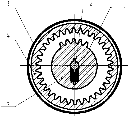
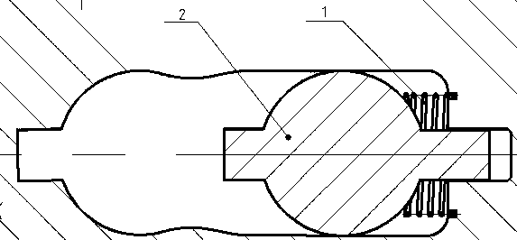
[0029] like figure 2 As shown, the meshing speed-limiting mechanism of the present invention includes a main shaft 2, an eccentric incomplete gear 5, a speed-limiting inner gear 4, a centrifugal spring 1, a cylindrical torsion spring 6 and a metal baffle 7, wherein the main shaft 2 is symmetrically processed with Flat key, the eccentric gear 5 is connected to the main shaft through the key on the main shaft, the metal baffle 7 is welded on the main shaft close to the end face of the eccentric gear, and the two ends of the torsion spring 6 are respectively fixed on the outer casing 3 and the speed-limiting inner gear ring 4 and fit on the spindle.
[0030] The meshing speed limiting mechanism is input by the main shaft, the eccentric gear is not eccentric at low speed or within the allowable working speed, and the input speed is directly transmitted to the ecce...
PUM
 Abstract
Description
Claims
Application Information
 - R&D
- Intellectual Property
- Life Sciences
- Materials
- Tech Scout
- Unparalleled Data Quality
- Higher Quality Content
- 60% Fewer Hallucinations
Browse by: Latest US Patents, China's latest patents, Technical Efficacy Thesaurus, Application Domain, Technology Topic, Popular Technical Reports.
© 2025 PatSnap. All rights reserved.Legal|Privacy policy|Modern Slavery Act Transparency Statement|Sitemap|About US| Contact US: help@patsnap.com