Dynamic differential pressure control valve

A technology of dynamic differential pressure and control valve, applied in the field of differential pressure control valve, can solve the problems of complex valve body structure, and achieve the effect of simplified valve body structure and easy installation.

Active Publication Date: 2016-08-17
HEFEI GENERAL MACHINERY RES INST
View PDF5 Cites 2 Cited by
  • Summary
  • Abstract
  • Description
  • Claims
  • Application Information

AI Technical Summary

Problems solved by technology

[0003] Some of the existing domestic differential pressure control valve products need to set up an independent drainage structure connected to the low pressure end of the controlled system outside the valve body, resulting in complex structure of the valve body

Method used


Image

  • Dynamic differential pressure control valve
  • Dynamic differential pressure control valve
  • Dynamic differential pressure control valve

Examples


Embodiment Construction

[0037] Below in conjunction with accompanying drawing, technical solution of the present invention is described:

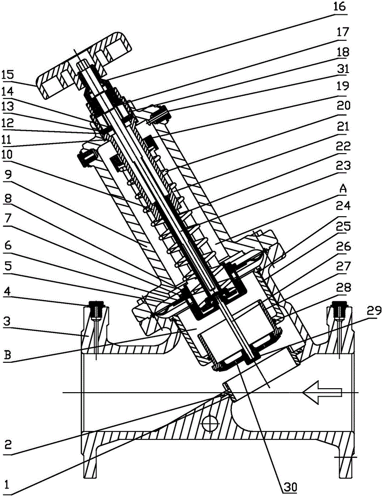
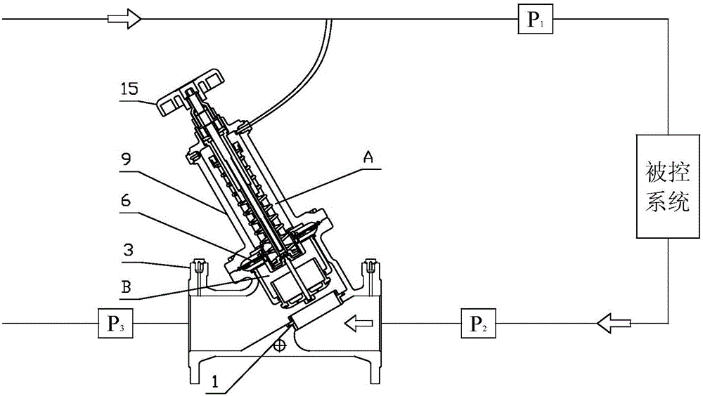
[0038] The present invention includes a valve body 3, which is provided with a fluid inlet and a fluid outlet, the fluid inlet communicates with the low-pressure end of the controlled system, and the internal flow channel of the valve body 3 is provided with a control valve that cooperates with the valve core 27 The valve seat 1 has a wide opening, and the valve body 3 is provided with a pressure-sensitive diaphragm 6. The two sides of the pressure-sensitive diaphragm 6 are the water supply high-pressure chamber A and the return water low-pressure chamber B respectively. The water supply high-pressure chamber A and the water supply high-pressure chamber The high-pressure end of the controlled system is connected, and the end surface of the valve core 27 is provided with a drainage hole 30 for introducing the fluid in the internal flow channel into the return water ...


PUM


Abstract

The invention relates to a dynamic differential pressure control valve. The dynamic differential pressure control valve comprises a valve body. The valve body is provided with a fluid inlet and a fluid outlet. The fluid inlet is communicated with the low-pressure end of a controlled system. A flow pass in the valve body is internally provided with a valve seat matched with a valve element to control the opening degree of a valve. The valve body is internally provided with a pressure sensing membrane. The two side faces of the pressure sensing membrane are provided with a water supply high-pressure cavity and a water return low-pressure cavity respectively, and the water supply high-pressure cavity is communicated with the high-pressure end of the controlled system. The end face of the valve element is provided with drainage holes for leading fluid in the internal flow pass into the water return low-pressure cavity. The valve body is internally provided with a spring component used for automatically controlling the differential pressure between the water supply high-pressure cavity and the water return low-pressure cavity. Due to the fact that the end face of the valve element is directly provided with the drainage holes, the purpose that the fluid in the internal flow pass in the valve body is led into the water return low-pressure cavity is achieved. According to the differential pressure control valve, the situation that a drainage structure is formed in the valve body is avoided, the structure of the valve body is simplified, and installation is convenient.

Description

technical field [0001] The invention belongs to the field of differential pressure control valves, in particular to a dynamic differential pressure control valve. Background technique [0002] The dynamic differential pressure control valve is a hydraulic control valve that can automatically adjust the constant pressure difference between the two ends of the controlled system without external power. It is mainly used in air conditioning systems and heating system end air conditioning boxes, fresh air units, various plate heat exchangers, In the branch pipe network of the air-conditioning chilled water system. [0003] Some existing domestic differential pressure control valve products require an independent drainage structure connected to the low-pressure end of the controlled system outside the valve body, resulting in a complicated valve body structure. Contents of the invention [0004] In order to solve the above technical problems, the present invention provides a dy...

Claims


Application Information

Patent Timeline
IPC IPC(8): F16K31/363
CPCF16K31/363
Inventor 张继伟范宜霖冯玉林雷艳章茂森靳淑军彭林
Owner HEFEI GENERAL MACHINERY RES INST
Why Eureka
Try Eureka