Blade Vibration Stress Distribution Calibration System and Method

A vibration stress and calibration method technology, applied in vibration testing, machine gear/transmission mechanism testing, measuring devices, etc., can solve the problem that the relative relationship between vibration stress is difficult to effectively determine, and achieve good vibration excitation effect, simple operation, and vibration excitation. Wide frequency range effect

Active Publication Date: 2018-09-11
CHINA AVIATION POWER MACHINE INST
View PDF5 Cites 0 Cited by
  • Summary
  • Abstract
  • Description
  • Claims
  • Application Information

AI Technical Summary

Problems solved by technology

[0004] The invention provides a blade vibration stress distribution calibration system and method to solve the technical problem that it is difficult to effectively determine the relative relationship between the position of the maximum stress point and other positions and the vibration stress at the maximum stress point in the existing blade vibration analysis

Method used


Image

  • Blade Vibration Stress Distribution Calibration System and Method
  • Blade Vibration Stress Distribution Calibration System and Method
  • Blade Vibration Stress Distribution Calibration System and Method

Examples


Embodiment Construction

[0047] It should be noted that, in the case of no conflict, the embodiments in the present application and the features in the embodiments can be combined with each other. The present invention will be described in detail below with reference to the accompanying drawings and examples.

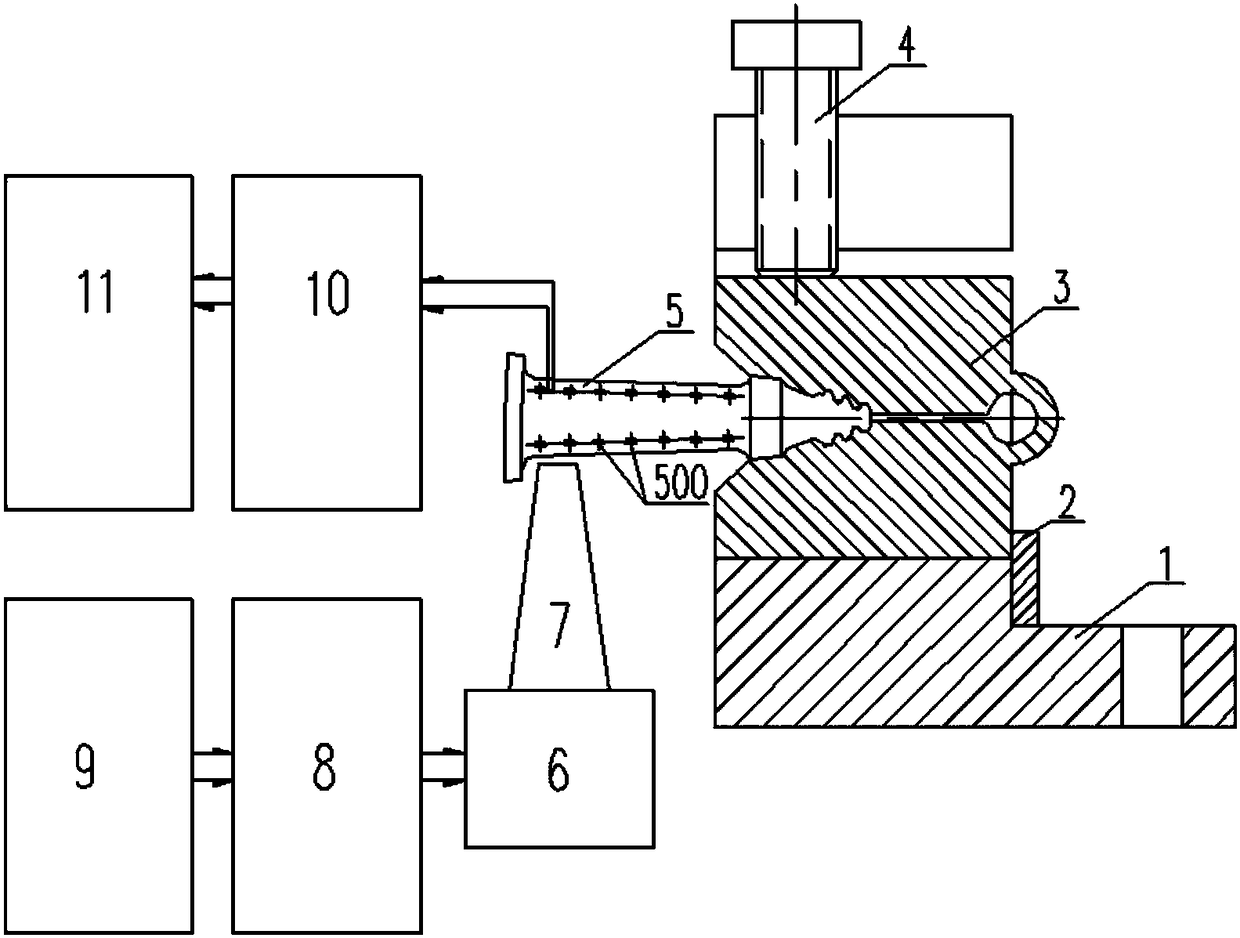
[0048] A preferred embodiment of the present invention provides a blade vibration stress distribution calibration system for calibrating the vibration stress distribution using an aeroengine blade as a test piece to be tested. The calibration system of this embodiment includes:

[0049] The blade fixing device is used to clamp and fix the test piece to be tested;

[0050] The signal excitation device is used to excite the resonance of the test piece to be tested according to the preset resonance frequency in the form of acoustic wave excitation;

[0051] The signal detection device is used to pick up the vibration strain at different positions of the test piece to be tested and perform data pr...


PUM


Abstract

The invention discloses a calibration system and a calibration method for blade vibration stress distribution. The calibration system comprises a blade fixing device, a signal exciting device and a signal detecting device, wherein the blade fixing device is used for clamping and fixing a to-be-detected test piece; the signal exciting device is used for exciting resonance of the to-be-detected test piece in a sound wave excitation mode according to preset resonance frequency; the signal detecting device is used for picking up vibration strain in different positions of the to-be-detected test piece and carrying out data processing, thus obtaining the vibration stress distribution under corresponding resonance frequency. According to the calibration system and the calibration method for the blade vibration stress distribution, disclosed by the invention, the to-be-detected test piece is clamped by the blade fixing device and is excited by the signal exciting device, the vibration strain in the different positions of the to-be-detected test piece can be picked up by the signal detecting device, the vibration stress distribution under the corresponding resonance frequency is obtained by the signal detecting device, and vibration stress calibration is scientific and effective; sound wave excitation is used as a non-contact type excitation mode, so that the operation is simple, regulation of an excitation position is convenient, the excitation frequency range is wide, the excitation effect is good, and the calibration system is suitable for vibration stress distribution calibration of a blade of an aviation engine.

Description

technical field [0001] The invention relates to the field of aeroengine blade detection, in particular to a blade vibration stress distribution calibration system and method. Background technique [0002] Aeroengine blade fatigue fracture failure is one of the main causes of aeroengine accidents. According to statistics, blade fatigue fracture has occurred in any aeroengine. Therefore, mastering the vibration characteristics and fatigue life of blades is of great significance to the safe operation of aero-engines. After the blade breaks, to find out the specific cause of the fracture failure, it is usually necessary to know the fatigue limit that the blade can withstand, the fatigue life of the blade under a given vibration stress, and the actual vibration stress level of the blade during the test run of the aeroengine. Further, it is necessary to carry out vibration fatigue test and vibration stress test on the blade. During the vibration fatigue test of the blade, it is ...

Claims


Application Information

Patent Timeline
Patent Type & Authority Patents(China)
IPC IPC(8): G01M7/02G01M13/02
CPCG01M7/02G01M13/028
Inventor 边杰
Owner CHINA AVIATION POWER MACHINE INST
Why Eureka
Try Eureka