Optical fiber defect detecting method and device

A technology of defect detection and defect location, which is applied in the field of detection, can solve the problems of large blind area of ​​optical fiber defect detection and measurement, poor detection accuracy, etc., and achieve accurate optical fiber defect detection, convenient implementation, and high cost performance

Active Publication Date: 2016-08-17
CHENGDU YINGXIN PHOTOELECTRIC TECH CO LTD
View PDF7 Cites 9 Cited by
  • Summary
  • Abstract
  • Description
  • Claims
  • Application Information

AI Technical Summary

Problems solved by technology

[0003] The purpose of the present invention is to provide a method and device for detecting optical fiber defects, so as to improve the problems of large blind areas and poor detection accuracy in optical fiber defect detection and measurement in the prior art

Method used


Image

  • Optical fiber defect detecting method and device
  • Optical fiber defect detecting method and device
  • Optical fiber defect detecting method and device

Examples


Embodiment Construction

[0046] In order to make the purpose, technical solutions and advantages of the embodiments of the present invention clearer, the technical solutions in the embodiments of the present invention will be clearly and completely described below in conjunction with the drawings in the embodiments of the present invention. Obviously, the described embodiments It is a part of embodiments of the present invention, but not all embodiments. The components of the embodiments of the invention generally described and illustrated in the figures herein may be arranged and designed in a variety of different configurations.

[0047] Accordingly, the following detailed description of the embodiments of the invention provided in the accompanying drawings is not intended to limit the scope of the claimed invention, but merely represents selected embodiments of the invention. Based on the embodiments of the present invention, all other embodiments obtained by persons of ordinary skill in the art wi...


PUM


Abstract

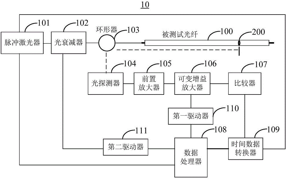
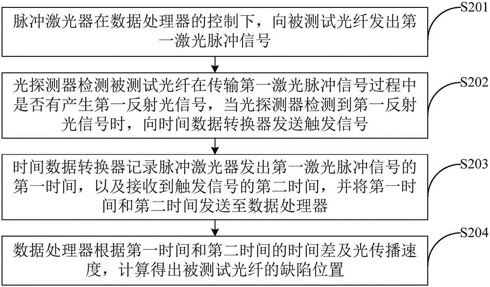
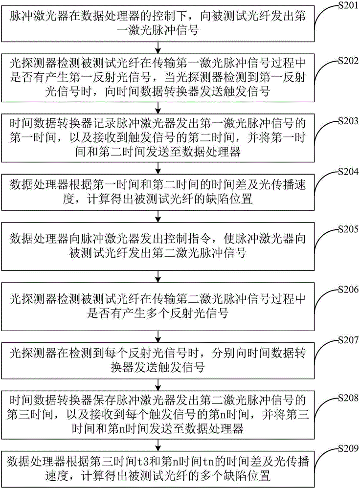
The invention provides an optical fiber defect detecting method and device. The optical fiber defect detecting device comprises a data processor, a pulse laser, a time data converter and an optical detector, wherein the pulse laser is used for emitting a laser pulse signal to a to-be-detected optical fiber under the control of the data processor; the optical detector is used for detecting whether the to-be-detected optical fiber generates a reflected light signal in the laser pulse signal transmission process and sends a trigger signal to the time data converter when detecting the reflected light signal; the time data converter is used for recording first time the pulse laser spent emitting the laser pulse signal and second time the pulse laser spent receiving the trigger signal and sends the first time and the second time to the data processor; the data processor is used for calculating positions of defects of the to-be-detected optical fiber according to the time difference between the first time and the second time as well as the light propagation speed. With the adoption of the optical fiber defect detecting method and device, the defects of the optical fiber can be detected conveniently and rapidly.

Description

technical field [0001] The present invention relates to the technical field of detection, in particular to a method and device for detecting optical fiber defects. Background technique [0002] With the rapid promotion and application of Fiber Channel (FC) network technology in defense and industrial applications such as aviation, aerospace, weapons, and ships, short-distance fiber optic wiring harnesses have become the main connection medium for Fiber Channel network devices. Since the optical fibers used in the short-distance clustered optical fiber harness have the characteristics of short distance length (usually less than 150 meters) and many physical connection points, how to realize the rapid inspection and maintenance of short-distance optical fiber connection defects has become an important issue in the application process of fiber channel networks. A technical question. At present, Optical Time Domain Reflectometer (OTDR) is mainly used to detect optical fiber def...

Claims


Application Information

Patent Timeline
Patent Type & Authority Applications(China)
IPC IPC(8): G01M11/00G01M11/08G01S17/06
CPCG01M11/088G01M11/3109G01S17/06
Inventor 楼英
Owner CHENGDU YINGXIN PHOTOELECTRIC TECH CO LTD
Why Eureka
Try Eureka