Technological cavity oxygen concentration detecting system and technological cavity oxygen concentration detecting method

A technology of oxygen concentration and detection system, which is applied in the field of gas pipeline control and semiconductor manufacturing, can solve the problems of uncertain nitrogen volume, inaccurate setting operation, uncertain degree of dilution, etc., to achieve consistency and avoid product defects Effect

Inactive Publication Date: 2016-08-17
SHANGHAI HUALI MICROELECTRONICS CORP
View PDF3 Cites 1 Cited by
  • Summary
  • Abstract
  • Description
  • Claims
  • Application Information

AI Technical Summary

Problems solved by technology

[0003] Due to the inaccurate setting operation, the amount of nitrogen gas flowing into the oxygen concentration detector is uncertain, which makes the degree of dilution of the gas sampled in the process chamber uncertain with nitrogen gas, which ultimately affects the detection of oxygen in the process chamber by the oxygen concentration detector. amount of error
[0004] At the same time, because the nitrogen setting cannot be guaranteed to be completely consistent between machines of the same type, the machines cannot be well matched with each other.

Method used


Image

  • Technological cavity oxygen concentration detecting system and technological cavity oxygen concentration detecting method
  • Technological cavity oxygen concentration detecting system and technological cavity oxygen concentration detecting method
  • Technological cavity oxygen concentration detecting system and technological cavity oxygen concentration detecting method

Examples


Embodiment Construction

[0026] In order to make the content of the present invention clearer and easier to understand, the content of the present invention will be described in detail below in conjunction with specific embodiments and accompanying drawings.

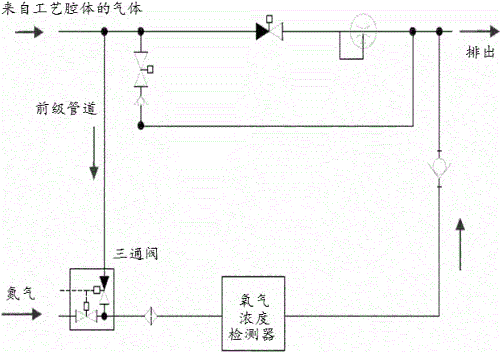
[0027] Currently, if figure 1 As shown, when detecting the oxygen concentration of the process chamber, the gas from the process chamber flows into the three-way valve through the foreline pipeline, and the nitrogen dilution circuit flows into the three-way valve at the same time, and the gas is mixed and then flows into the oxygen concentration detector for detection . When the oxygen concentration is higher than the set value of the process parameters, the process chamber is fed with nitrogen to dilute until the concentration measured by the oxygen concentration detector is lower than the set value of the process, the detection of the oxygen concentration is stopped, and the three-way valve is closed. The process chamber starts the subsequent...


PUM


Abstract

The invention provides a technological cavity oxygen concentration detecting system and a technological cavity oxygen concentration detecting method. The technological cavity oxygen concentration detecting system comprises a foreline, a three-way valve, a mass flow controller and an oxygen concentration detector. Gas from a technological cavity is introduced into the first input end of the three-way cavity through the foreline, the mass flow controller is installed at the second input end of the three-way valve, and the second input end of the three-way valve receives nitrogen making the temperature of gas from the technological cavity reduced, and the output end of the three-way valve is connected to the oxygen concentration detector.

Description

technical field [0001] The invention relates to the field of semiconductor manufacturing, in particular to the technical field of gas pipeline control; more specifically, the invention relates to a process chamber oxygen concentration detection system and a process chamber oxygen concentration detection method. Background technique [0002] At present, the nitrogen cleaning flow rate of the oxygen concentration detector is generally set to be less than 5ppm, but the minimum range of the actual monitoring indicator that can be adjusted is 50ppm. As a result, engineers can only roughly judge that the pointer is close to the scale 0 when adjusting the flow rate. , and finally the process department uses the test wafer to judge whether the nitrogen purge flow rate of the oxygen concentration detector is set normally. [0003] Due to the inaccurate setting operation, the amount of nitrogen gas flowing into the oxygen concentration detector is uncertain, which makes the degree of ...

Claims


Application Information

Patent Timeline
Patent Type & Authority Applications(China)
IPC IPC(8): G01N33/00
CPCG01N33/0009G01N33/0018
Inventor 顾海龙裴雷洪严骏
Owner SHANGHAI HUALI MICROELECTRONICS CORP
Why Eureka
Try Eureka