A Temperature Compensation System for CNC Machine Tool

A temperature compensation, CNC machine tool technology, applied in the field of CNC machine tools, can solve the problems of no pre-installed temperature sensor and difficult temperature data acquisition, and achieve the effect of reducing labor costs and improving machining accuracy

Active Publication Date: 2018-05-15
ANHUI PROVINCE JIEYONGDA INTELLIGENT MACHINE
View PDF7 Cites 0 Cited by
  • Summary
  • Abstract
  • Description
  • Claims
  • Application Information

AI Technical Summary

Problems solved by technology

However, many machine tools are not pre-installed with temperature sensors due to various problems during assembly, which makes it difficult to collect temperature data.

Method used


Image

  • A Temperature Compensation System for CNC Machine Tool

Examples


Embodiment 1

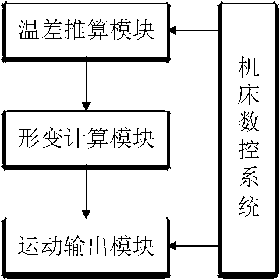
[0024] refer to figure 1 , a temperature compensation system for a numerically controlled machine tool proposed by the present invention, comprising: a temperature difference calculation module, a deformation calculation module and a motion output module.

[0025] The temperature difference calculation model is preset in the temperature difference calculation module, and the temperature difference calculation model is:

[0026] Among them, T i is the current temperature difference, T i-1 is the temperature difference at the latest speed change of the moving shaft, V i is the current movement speed of the movement axis, V i-1 is the movement speed of the movement axis before the latest speed change, and Δt is the movement time at the current movement speed;

[0027] When V i >V i-1 , G(V i )>1, specifically, G(V i ) = V i / (V i -V i-1 ); when V i i-1 , 0i )i ) = (V i-1 -V i ) / V i-1 .

[0028] f(Δt)=k×Δt, k is a calculation constant, and is a positive number, a...

Embodiment 2

[0039]The difference between this embodiment and Embodiment 1 is that there is no preset deformation calculation model in the deformation calculation module. In this embodiment, a deformation temperature difference mapping set is preset in the deformation calculation module, and the deformation temperature difference mapping set includes a plurality of subsets, and each subset includes a temperature difference value and a deformation value. The deformation calculation module obtains the corresponding deformation value according to the current temperature difference as the deformation amount of the target motion axis.

[0040] In this embodiment, the corresponding relationship between the temperature difference value and the deformation value can be obtained through experimental measurement. Compared with Embodiment 1, this embodiment needs to consume a lot of manpower and time costs in the early stage to collect and arrange deformation temperature difference mapping sets, but,...


PUM


Abstract

The invention discloses a numerically-controlled machine tool temperature compensation system. The numerically-controlled machine tool temperature compensation system comprises a temperature difference calculation module, a deformation calculation module and a movement output module, wherein the temperature difference calculation module is connected with a machine tool numerical control system, acquires the motion state of a target movement shaft through the machine tool numerical control system and calculates the current temperature difference according to the motion state of the target movement shaft and the temperature difference calculation module, and the deformation calculation module is connected with the temperature difference calculation module and acquires the deformation amount of the target movement shaft according to the current temperature difference; the movement output module is connected with the machine tool numerical control system and the deformation calculation module, acquires the movement amount output by the machine tool numerical control system, and compensates for the movement amount according to the deformation amount so as to generate and output a movement target value. According to the numerically-controlled machine tool temperature compensation system, the deformation amount of a machine tool can be indirectly obtained through motion state by means of the temperature difference calculation module, and the motion state can be directly obtained through the machine tool numerical control system; therefore, the deformation amount of the machine tool can be calculated automatically and intelligently.

Description

technical field [0001] The invention relates to the technical field of numerical control machine tools, in particular to a temperature compensation system for numerical control machine tools. Background technique [0002] When the machine tool is running, there is relative motion between the transmission parts, and the frictional heat of the machine tool screw, nut seat, bearing, etc., causes the thermal expansion of the machine tool components, and the movement of each movement axis deviates from the target, resulting in machine tool processing errors. To solve the above problems, it is necessary to monitor the temperature change of each transmission part, and then calculate the error value of the machine tool displacement according to the relative relationship between the deformation of each transmission part and the temperature change, and then compensate it in the numerical control system to achieve the purpose of compensating the temperature rise of the machine tool . ...

Claims


Application Information

Patent Timeline
Patent Type & Authority Patents(China)
IPC IPC(8): G05B19/404
CPCG05B19/404G05B2219/37509
Inventor 毛益飞杨纪村葛峰王宇石云张帝
Owner ANHUI PROVINCE JIEYONGDA INTELLIGENT MACHINE
Why Eureka
Try Eureka