Rotor dual-side permanent-magnet type single-winding dual-stator vernier motor

A vernier motor, single-winding technology, used in motors, magnetic circuits, electromechanical devices, etc., can solve the problems of low utilization rate of permanent magnets and small output torque, and achieve high utilization rate of stator slots, increased torque output capability, simple structure

Inactive Publication Date: 2016-08-17
HARBIN UNIV OF SCI & TECH
View PDF7 Cites 7 Cited by
  • Summary
  • Abstract
  • Description
  • Claims
  • Application Information

AI Technical Summary

Problems solved by technology

[0004] In order to solve the problems of small output torque and low utilization rate of permanent magnets in traditional vernier motors, the present invention proposes a double-sided permanent magnet type single-winding double-stator vernier motor

Method used


Image

  • Rotor dual-side permanent-magnet type single-winding dual-stator vernier motor
  • Rotor dual-side permanent-magnet type single-winding dual-stator vernier motor
  • Rotor dual-side permanent-magnet type single-winding dual-stator vernier motor

Examples


specific Embodiment approach 1

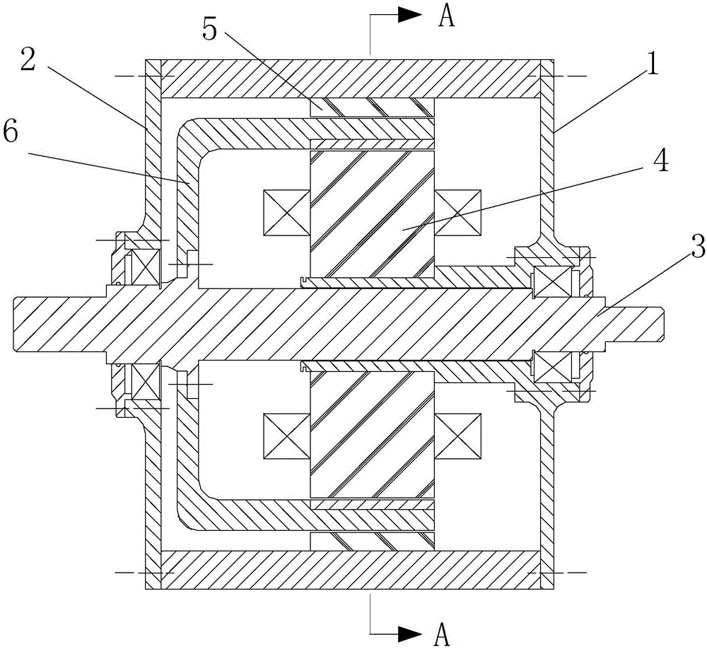
[0016] Specific implementation mode 1. Combination Figure 1 to Figure 3 Describe this specific embodiment, the rotor double-sided permanent magnet type single-winding double-stator vernier motor described in this specific embodiment includes an inner stator 4, an outer stator 5, a rotor 6, a rotor output shaft 3, a left end cover 2 and a right end cover 1. The inner end of the inner stator 4 is fixedly connected with the right end cover 1, and the rotor output shaft 3 is arranged in the center hole of the right end cover 1, and one end of the rotor output shaft 3 is supported in the inner hole of the left end cover 2 through a bearing, and the rotor output shaft 3 The other end of the rotor is supported in the inner hole of the right end cover 1 through a bearing. The rotor 6 is a cup-shaped rotor. The cup bottom of the rotor 6 is fixedly connected with the rotor output shaft 3. The cup body of the rotor 6 is located between the inner stator 4 and the outer stator 5. Between,...

specific Embodiment approach 2

[0024] Embodiment 2. The difference between this embodiment and the permanent-magnet double-rotor single-winding double-stator vernier motor described in Embodiment 1 is that the N is 12.

specific Embodiment approach 3

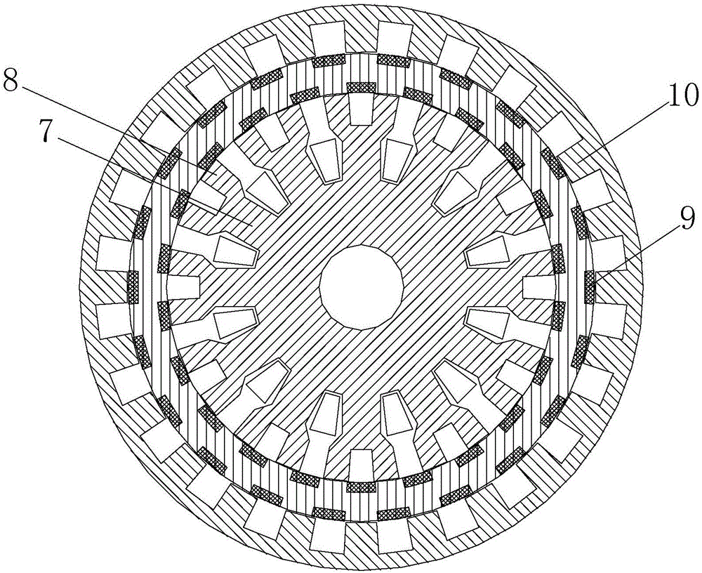
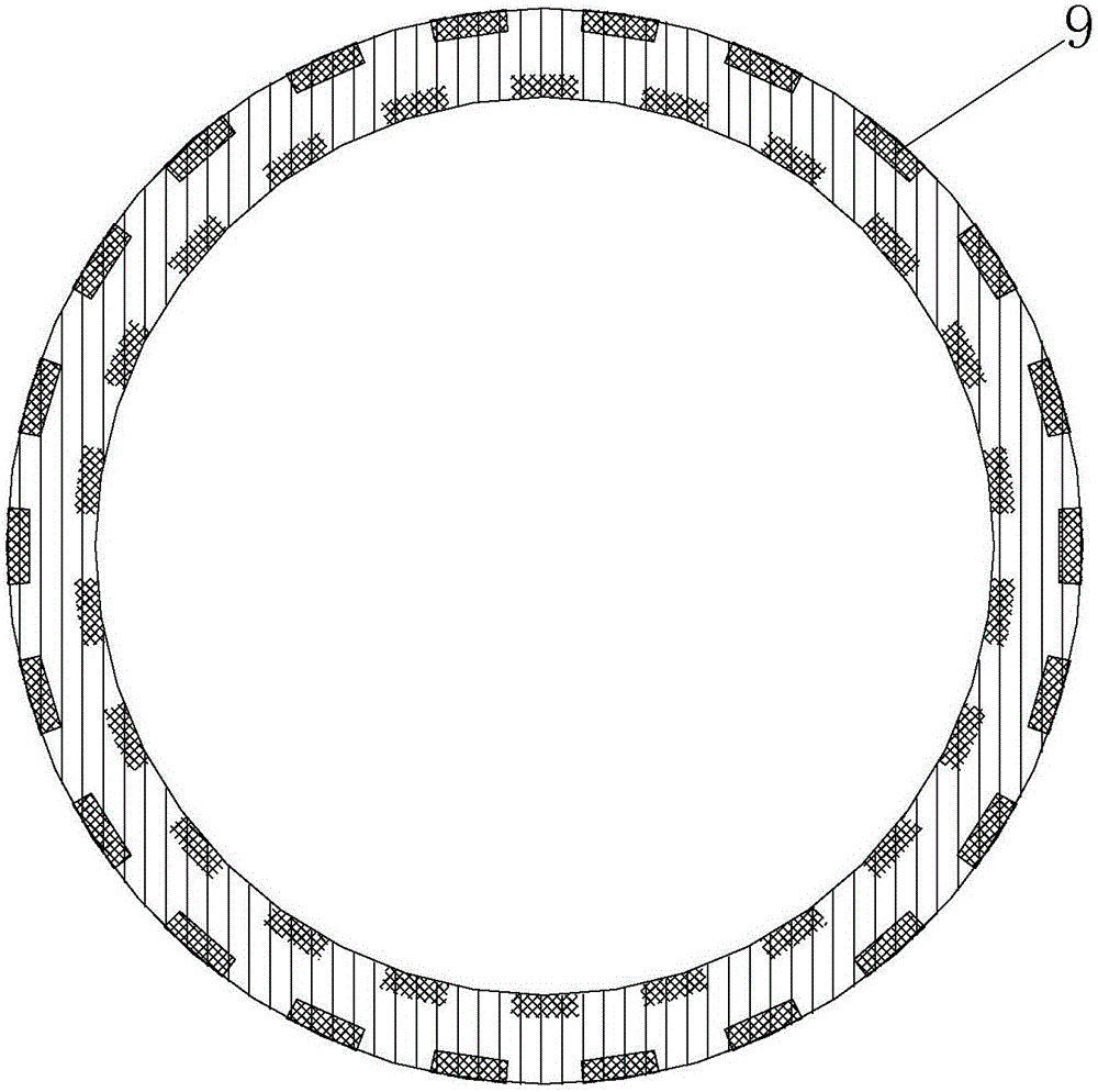
[0025] Embodiment 3. The difference between this embodiment and the double-sided permanent magnet single-winding double-stator vernier motor described in Embodiment 1 is that the permanent magnet 9 embedded in the rotor 6 is a sintered NdFeB magnet.


PUM


Abstract

The invention discloses a rotor dual-side permanent-magnet type single-winding dual-stator vernier motor, relates to the field of a vernier motor and aims to solve the problems of small output torque and low permanent-magnet utilization ratio of a traditional vernier motor. A rotor is a cup-shaped rotor, the cup bottom is fixedly connected with a rotor output shaft, the cup body is arranged between an inner stator and an outer stator, N pairs of magnetic flux modulation units are arranged on the inner stator, in each pair of magnetic flux modulation units, the bottom of a modulation rod is fixed on the external circular surface of the inner stator, a three-phase armature winding is wound around the modulation rod, two modulation teeth are symmetrically fixed at the two sides of the top of the modulation rod, the distance between each adjacent two pairs of magnetic flux modulation units is the same as the distance between the two modulation teeth, the rotor is formed by laminating silicon steel sheets, slot positions are arranged on the upper surface and the lower surface of the rotor, permanent magnets are embedded into the slot positions, the permanent magnets at the upper part and the permanent magnets at the lower part are sequentially arranged in a staggered way, 2N stator teeth on the inner surface of the outer stator and the modulation teeth are different by a tooth pitch in spatial arrangement. The rotor dual-side permanent-magnet type single-winding dual-stator vernier motor has the advantages of large output torque and high permanent-magnet utilization ratio, and is applicable to the field such as an electric vehicle.

Description

technical field [0001] The invention relates to the field of vernier motors. Background technique [0002] In recent years, direct drive, which can save the mechanical gear transmission system, has become a research hotspot in the industry. Although traditional direct drive motors can reduce mechanical loss, noise, and improve efficiency and reliability, in order to obtain greater torque, the volume is generally larger, and the cost of control circuit components has also increased. [0003] The vernier motor based on the principle of magnetic flux modulation has attracted more and more scientific researchers' attention because of its simple structure, reliable operation and high torque density. The vernier motor can realize low-speed high-torque output, especially suitable for applications requiring direct drive such as wind power generation, ship propulsion, and electric vehicles. Although the traditional vernier motor can be used as a direct drive motor, it still has the...

Claims


Application Information

Patent Timeline
Patent Type & Authority Applications(China)
IPC IPC(8): H02K16/04H02K1/27H02K1/14
CPCH02K1/146H02K1/278H02K16/04H02K2213/03Y02T10/64
Inventor 谢颖黑亮声张岩蔡翔李飞单雪婷
Owner HARBIN UNIV OF SCI & TECH
Why Eureka
Try Eureka