Moving-coil brushless DC (direct-current) permanent magnet motor with inner and outer rotor structure
A permanent magnet motor and hollow cup technology, which is applied to electric components, electrical components, electromechanical devices, etc., can solve the problems of poor winding effect of armature winding wire cups, insufficient use of wire space, and low air gap magnetic density, etc. Achieve the effect of increasing the air-gap magnetic flux density, improving the air-gap magnetic flux density, and improving operating efficiency
- Summary
- Abstract
- Description
- Claims
- Application Information
AI Technical Summary
Problems solved by technology
Method used
Image
Examples
Embodiment 1
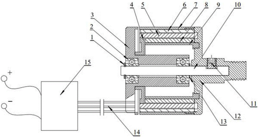
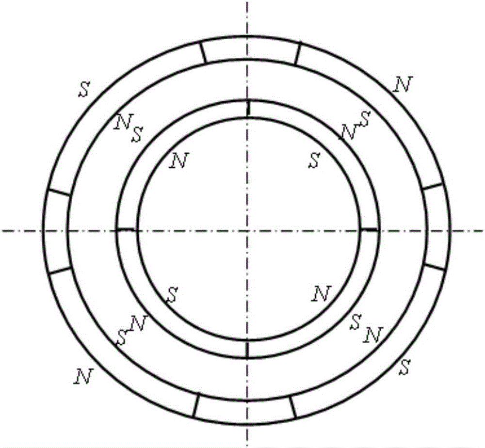
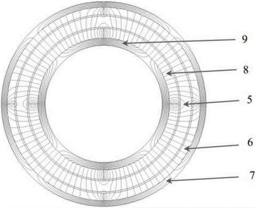
[0033] figure 1 The cross-sectional view of the hollow cup armature inner and outer rotor brushless DC permanent magnet motor provided by the present invention includes a shafting assembly and a moving assembly, and the shafting assembly includes a rotating shaft 10, a bearing 2, a first end cover 3, a hollow cup stator 5 and a The blue plate 4, the moving assembly includes the casing 7, the outer permanent magnet 6, the inner permanent magnet 8, the magnetic conduction ring 9 and the second end cover 12, the hollow cup stator 5 is composed of a cup-shaped skeleton and windings, the left side of the hollow cup stator 5 The end is further fixedly connected with the first end cover 3 by connecting the upper end side of the flange 4, and keeps absolutely still under the working state of the motor. The radial inner side of the hollow cup stator 5 is the inner permanent magnet 8, and the radial outer side of the hollow cup stator 5 is the outer permanent magnet 6; On the inner wal...
Embodiment 2
[0049] The hollow cup armature inner and outer rotor brushless DC permanent magnet motor provided in this embodiment is a permanent magnet motor with a Hall element, and its shaft assembly and moving assembly have the same structure as the permanent magnet motor without a Hall element in Embodiment 1. Similarly, a PCB board 16 , a Hall element 17 and lead wires 18 are added on the basis of the structure of the permanent magnet motor in Embodiment 1.
[0050] Figure 6 It is a cross-sectional view of a hollow cup armature inner and outer rotor brushless DC permanent magnet motor provided in this embodiment, including a shaft assembly and a moving assembly. The shaft assembly includes a shaft 10, a bearing 2, a first end cover 3, The hollow cup stator 5 and the flange 4, the moving assembly includes the casing 7, the outer permanent magnet 6, the inner permanent magnet 8, the magnetic conducting ring 9 and the second end cover 12, and the hollow cup stator 5 is composed of a cup...
Embodiment 3
[0054] The difference between the coreless armature inner rotor brushless DC permanent magnet motor structure provided in this embodiment and the permanent magnet motor structure in Embodiment 1 is that the winding of the coreless stator 5 winding is a series stacked Y-shaped connection.
[0055] Figure 7 It is a schematic diagram of the hollow cup winding series stacked Y-shaped connection method of the hollow cup armature inner and outer rotor brushless DC permanent magnet motor of the present invention. The finished wire package has the wire heads A, B, C and wire tails X, Y, Z of the three-phase winding. B and C are connected in series to increase the number of turns of each phase winding, forming a form of windings stacked in series.
[0056] The hollow cup stator 5 is machine wound on the skeleton, including winding methods such as winding, oblique winding and assembled winding. The wire cup conductors can be arranged in succession in long strips, and the wire head and...
PUM
 Abstract
Description
Claims
Application Information
 - R&D
- Intellectual Property
- Life Sciences
- Materials
- Tech Scout
- Unparalleled Data Quality
- Higher Quality Content
- 60% Fewer Hallucinations
Browse by: Latest US Patents, China's latest patents, Technical Efficacy Thesaurus, Application Domain, Technology Topic, Popular Technical Reports.
© 2025 PatSnap. All rights reserved.Legal|Privacy policy|Modern Slavery Act Transparency Statement|Sitemap|About US| Contact US: help@patsnap.com


