
Rotor Position Estimation Method for Three-stage Motor Based on Variation of Salient Pole Characteristics

A technology of motor rotor and salient pole characteristics, which is applied in the direction of generator circuit layout control, generator control, synchronous generator control, etc. and large changes in armature current

Active Publication Date: 2018-06-01
NORTHWESTERN POLYTECHNICAL UNIV
View PDF4 Cites 0 Cited by
  • Summary
  • Abstract
  • Description
  • Claims
  • Application Information

AI Technical Summary

Problems solved by technology

At this time, the high-frequency injection method based on saliency cannot accurately obtain the position signal in the area near the disappearance of the saliency of the motor.
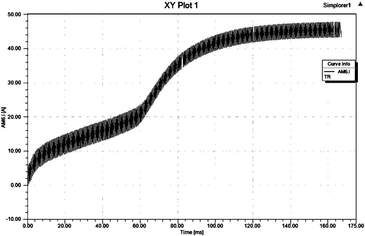
[0005] The excitation current and armature current of the three-stage motor change greatly during the starting process, and the salient pole characteristics of the main generator change greatly during the starting process. The traditional rotor initial position detection algorithm cannot realize the rotor position estimation of this type of motor.
[0007] However, the mechanical and electromagnetic coupling of the three-stage motor is relatively serious. At the same time, the saturation characteristics of the motor change with the change of the motor current. The above method is more sensitive to the electromagnetic interference and salient pole characteristics of the motor.

Method used


Image

  • Rotor Position Estimation Method for Three-stage Motor Based on Variation of Salient Pole Characteristics
  • Rotor Position Estimation Method for Three-stage Motor Based on Variation of Salient Pole Characteristics
  • Rotor Position Estimation Method for Three-stage Motor Based on Variation of Salient Pole Characteristics

Examples


Embodiment Construction

[0026] The present invention will now be further described in conjunction with the embodiments and drawings:

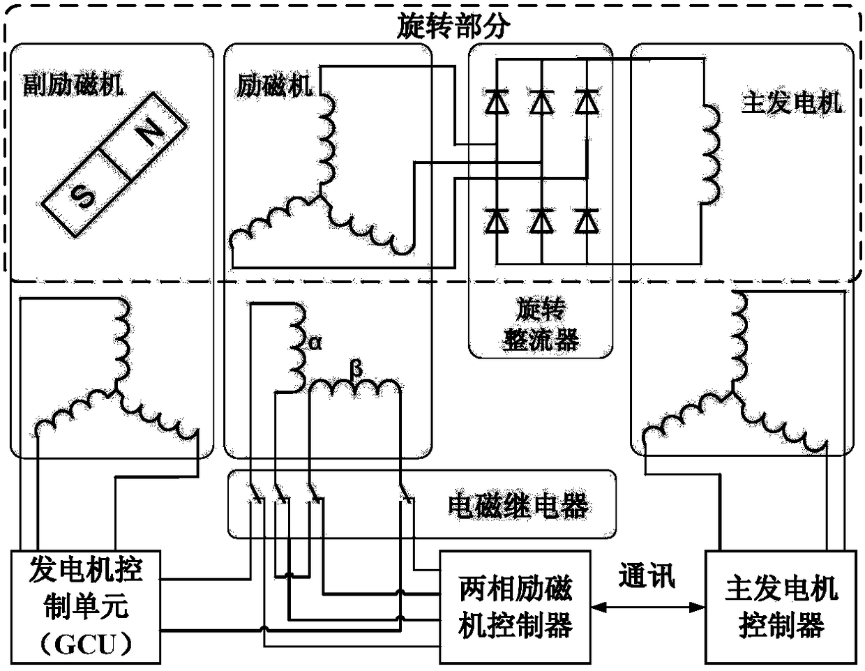
[0027] In this embodiment, a pulsating high-frequency voltage is applied to the stator end of the main generator, and then the pulsating high-frequency voltage is extracted from the stator winding of the exciter to realize the detection of the rotor position. It contains the following steps in sequence: (The detection principle of the two-phase excitation structure and the three-phase excitation structure are the same. The present invention takes the three-stage motor of the two-phase excitation structure as an example for description)

[0028] 1. The rotor winding of the main generator must be excited first, and the alternating current with a difference of 90 degrees is fed into the stator winding of the two-phase exciter. The above alternating voltage will form a rotating magnetic field on the stator winding of the exciter, and the rotor winding of the magnet The general...


PUM


Abstract

The invention relates to a third-level type motor rotor position estimation method for salient pole characteristic change. Targeted to characteristics of a third-level type motor multi-level combination structure, a new signal transfer and detection channel is established between a main generator and an exciter and is shown as the graph 2; high-frequency signals are injected on the stator side of the main generator through the signal transfer channel, the signals sequentially pass through a main generator air-gap magnetic field, a rotating rectifier and an exciter air-gap magnetic field, then high-frequency response signals are extracted out of an exciter stator winding, and estimation of the position of a motor rotor is achieved. According to the main generator injection-exciter detection signal transfer and detection thought, the characteristic that mutual inductance between the main generator stator winding and the exciter winding changes along with the position of the rotor is fully utilized, and the position of the main generator exciter winding, namely the position of the rotor magnetic pole is estimated. The estimation method does not depend on salient polarity of a motor, and the method is still applicable when the main generator salient polarity changes in the starting process.

Description

Technical field [0001] The invention belongs to the technical field of AC motor transmission, and relates to a method for estimating the rotor position of an aviation three-stage synchronous motor (hereinafter referred to as a three-stage motor), and in particular to a method for estimating the rotor position of a three-stage motor with salient pole characteristics. Background technique [0002] At present, three-stage brushless synchronous motors (hereinafter referred to as three-stage motors) are mostly used in domestic and foreign aviation AC power systems as generators to provide electric power energy for airborne equipment. In the current aircraft in my country, the generator does not have the function of starting aero-engines. The research on the integrated starter and power generation system with starting function is of great significance for reducing the volume and weight of the system, simplifying the system structure, and improving the system integration. Hot issues in t...

Claims


Application Information

Patent Timeline
Patent Type & Authority Patents(China)
IPC IPC(8): H02P9/00H02P103/20H02P101/30
CPCH02P9/009H02P2101/30H02P2103/20
Inventor 彭纪昌刘卫国焦宁飞孙承浩
Owner NORTHWESTERN POLYTECHNICAL UNIV
Learn More