Supercharge Your Innovation With Domain-Expert AI Agents!

A metal pipe automatic feeding device

A technology of automatic feeding and metal pipes, applied in the direction of feeding device, positioning device, storage device, etc., can solve the problems of manual pushing and feeding, time-consuming and laborious, etc., and achieve the effect of convenient disassembly and assembly and simple structure

Active Publication Date: 2018-04-13
ANHUI GUIDA AUTO PARTS
View PDF7 Cites 0 Cited by
  • Summary
  • Abstract
  • Description
  • Claims
  • Application Information

AI Technical Summary

Problems solved by technology

[0002] At present, in the production of auto parts, it is necessary to process various pipe fittings, and these pipe fittings are basically completed by cutting a long raw metal pipe into sections, pressing molds and other processes. When cutting a long metal pipe, it is necessary Manually lift the metal long tube to the cutting machine, and after cutting for a while, it needs to be manually pushed and fed, which is very time-consuming and laborious

Method used


Image

  • A metal pipe automatic feeding device
  • A metal pipe automatic feeding device
  • A metal pipe automatic feeding device

Examples


Embodiment Construction

[0022] Below, the technical solution of the present invention will be described in detail through specific examples.

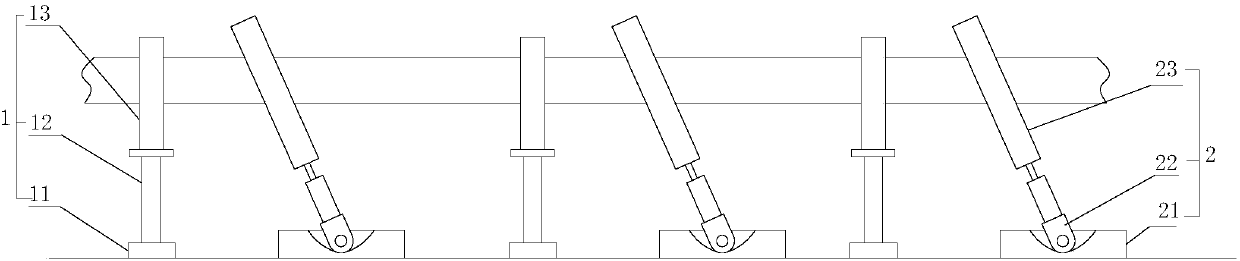
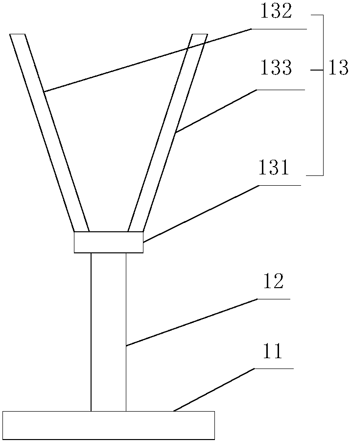
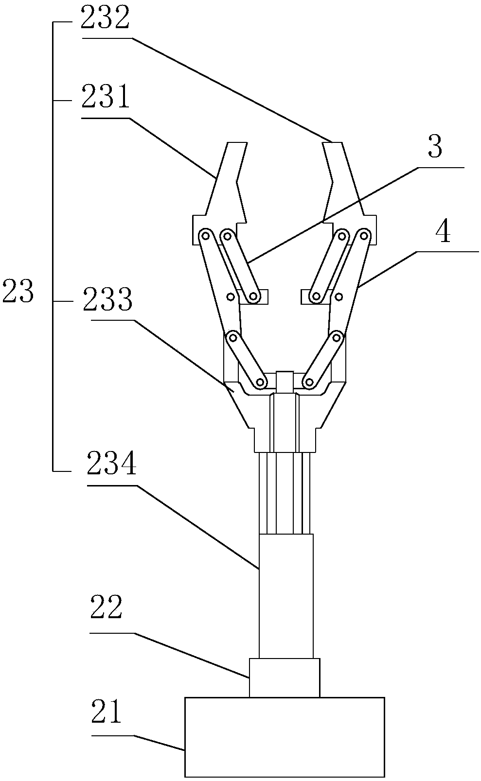
[0023] Such as Figure 1-3 as shown, figure 1 It is a structural schematic diagram of a metal pipe automatic feeding device proposed by the present invention; figure 2 It is a structural schematic diagram of the bracket in a metal pipe automatic feeding device proposed by the present invention; image 3 It is a structural schematic diagram of the advancing mechanism of a metal pipe automatic feeding device proposed by the present invention.

[0024] refer to Figure 1-3 , an automatic feeding device for metal pipes proposed by an embodiment of the present invention, including: a bracket group and a driving mechanism,

[0025] The bracket group includes N brackets 1 arranged in a straight line, N≥2, and N is a natural number; the bracket 1 includes a base 11 arranged horizontally, a column 12 vertically fixed on the base 11, installed on the top of the col...


PUM


Abstract

The invention discloses an automatic metal pipeline feeding device. The automatic metal pipeline feeding device comprises a bracket set and a driving mechanism, wherein the bracket set comprises N brackets linearly arranged; N is greater than or equal to 2 and is a natural number; any two adjacent brackets are provided with progressive mechanisms; each progressive mechanism comprises a base horizontally arranged, a swinging seat arranged on the base and swinging along the arrangement direction of the brackets, and a mechanical clamping hand arranged on the swinging seat and capable of swinging along with the swinging of the swinging seat; and the driving mechanism is used for driving the swinging seats of the progressive mechanisms to swing simultaneously in the same direction. The automatic metal pipeline feeding device has the beneficial effects that pipe fittings are held through mutual matching of the brackets linearly arranged; the pipe fittings are transferred along the arrangement direction of the brackets by mutual matching of the progressive mechanism arranged between the two adjacent brackets and the driving mechanism, thereby realizing the automatic feeding of the pipe fittings; and manual pushing and feeding are not needed, thereby saving time and labor.

Description

technical field [0001] The invention relates to the technical field of processing equipment for automobile pipe fittings, in particular to an automatic feeding device for metal pipes. Background technique [0002] At present, in the production of auto parts, it is necessary to process various pipe fittings, and these pipe fittings are basically completed by cutting a long raw material metal pipe into sections, pressing molds and other processes. When cutting a long metal pipe, it is necessary Manually lift the long metal tube to the cutting machine, and after cutting a section, it needs to be manually pushed and fed, which is very time-consuming and laborious. Contents of the invention [0003] Based on the technical problems in the above background technology, the present invention proposes an automatic feeding device for metal pipes. [0004] The invention proposes an automatic feeding device for metal pipes, including: a bracket group and a driving mechanism, [0005]...

Claims


Application Information

Patent Timeline
Patent Type & Authority Patents(China)
IPC IPC(8): B21D43/10
CPCB21D43/006B21D43/105
Inventor 林和平
Owner ANHUI GUIDA AUTO PARTS
Features
  • R&D
  • Intellectual Property
  • Life Sciences
  • Materials
  • Tech Scout
  • Unparalleled Data Quality
  • Higher Quality Content
  • 60% Fewer Hallucinations
Learn More