Supercharge Your Innovation With Domain-Expert AI Agents!

Circumference error compensation method using laser direct feedback

An error compensation, laser direct technology, applied in the field of circular error compensation, can solve the problems of excessive points that cannot be compensated and recorded, slow measurement, uncertain compensation data, etc., to improve the efficiency of linear position compensation, simple structure, and linear compensation accuracy. improved effect

Inactive Publication Date: 2016-08-24
KEDE NUMERICAL CONTROL CO LTD
View PDF6 Cites 3 Cited by
  • Summary
  • Abstract
  • Description
  • Claims
  • Application Information

AI Technical Summary

Problems solved by technology

[0010] First of all, due to the fixed distance stop method, it is necessary to use the pause to make the laser interferometer detect the fixed stop point, so the measurement is slow
[0011] Second, because the fixed displacement pause method is used to realize the detection record of the position point, the position that can be recorded is only a fixed pause stop point, and the transition point in the middle cannot be compensated and recorded. It can only be considered as a continuous linear error and an estimated value is used for compensation.
[0012] Third, the expectation of compensation is to compensate the errors of the entire measurement link and the motion execution link, but when the motion platform is running and stopping, due to the application of the position closed loop, it usually has a small jitter within a range, so the laser interferometer The recorded value is mechanical deviation + control noise
Make the compensation data have an uncertainty

Method used


Image

  • Circumference error compensation method using laser direct feedback
  • Circumference error compensation method using laser direct feedback

Examples


Embodiment Construction

[0023] In order to make the purpose, technical solutions and advantages of the embodiments of the present invention more clear, the technical solutions in the embodiments of the present invention are clearly and completely described below in conjunction with the drawings in the embodiments of the present invention:

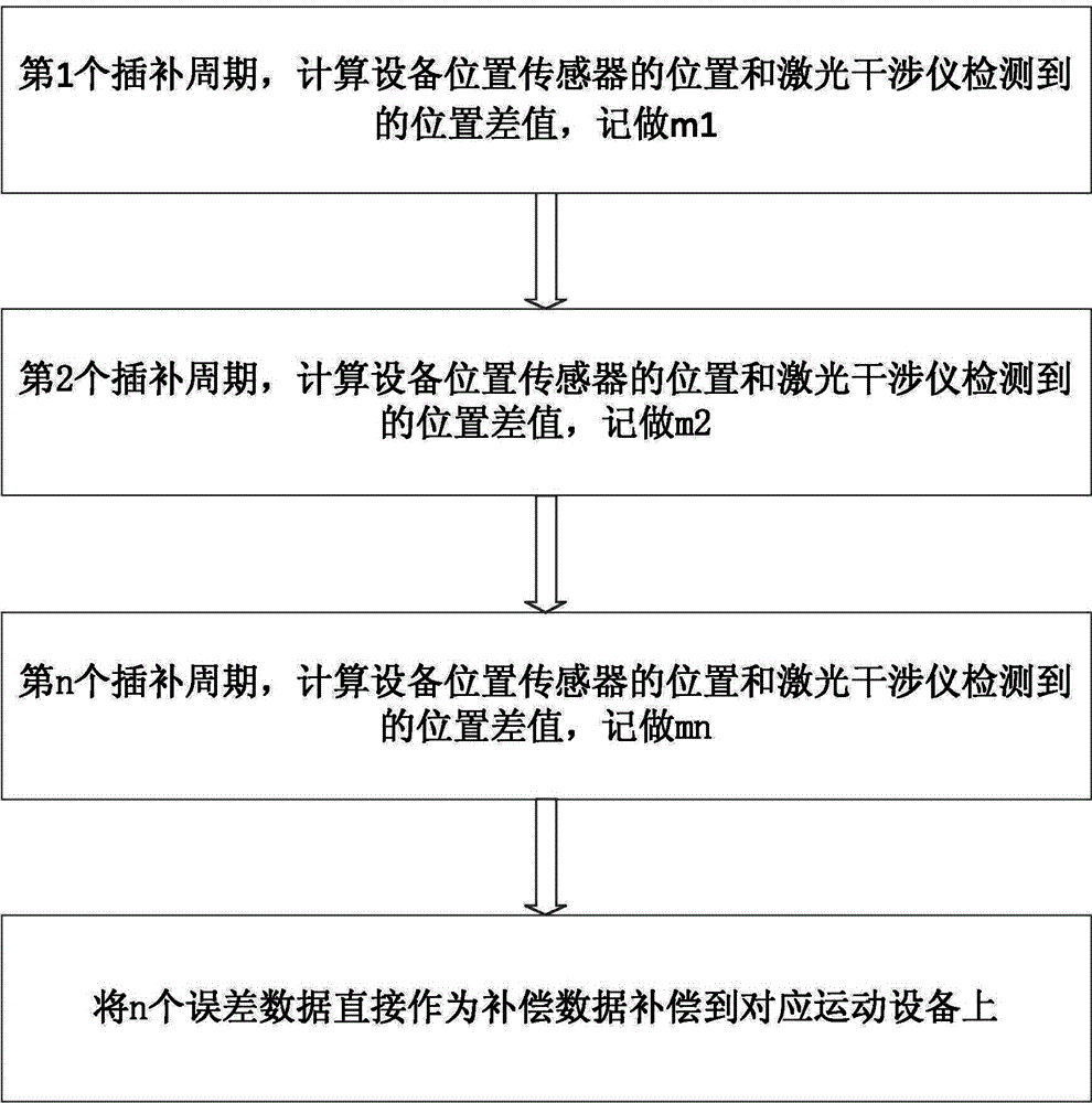
[0024] Such as figure 2 Shown: a circular error compensation method using laser direct feedback, using the laser interferometer motion position information output interface, directly introduce the precise position of the laser interferometer into the motion control system, the entire error compensation process becomes

[0025] First, connect the position information output interface of the laser interferometer to the motion control system to read the current circular motion position I of the machine tool detected by the laser interferometer.

[0026] Write a uniform circular running program corresponding to the measuring unit. Use the numerical control system to...


PUM


Abstract

The invention discloses a circular error compensation method using laser direct feedback, which has the following steps: - read the current circular motion position I of the machine tool detected by the laser interferometer; - record the position I output by the displacement sensor of the machine tool motion control system at the same moment Circular motion position II; - Calculate and record the difference between the circular motion position I and the circular motion position II obtained by the motion position of the laser interferometer and the detection of the encoder at the same moment; - Repeat the above steps to obtain each moment The sum of the differences is used as the error compensation of the system as a whole; and then the error compensation of the motion control system is performed. Compared with the traditional linear error compensation method, the linear position compensation efficiency will be greatly improved, and the linear compensation accuracy will be greatly improved. Moreover, the technology adopted is mature and the structure is relatively simple, which is very suitable for wide-scale popularization and use in the field of precision numerical control machine tools.

Description

technical field [0001] The invention relates to a method for compensating the circumference error during the movement of a machine tool, in particular to a method for compensating the circumference error by using laser direct feedback. Involving patent classification number B23 machine tools; parts, components or accessories of metalworking B23Q machine tools not included in other categories, such as profiling devices or control devices. B23Q23 / 00 is used to compensate unevenness or wear, such as guide rails and positioning mechanisms. Background technique [0002] In the feed transmission chain of CNC machine tools, gear transmission, ball screw: nut pairs, etc. all have backlash. The existence of this backlash will cause the servo motor to idle while the table does not actually move when the machine tool moves in the reverse direction. . For CNC machine tools using a semi-closed-loop servo system, the existence of backlash will affect the positioning accuracy and repeat ...

Claims


Application Information

Patent Timeline
IPC IPC(8): B23Q15/013B23Q23/00
Inventor 张赞秋于德海于本宏吴淇孙振高岩叶东国吴福海
Owner KEDE NUMERICAL CONTROL CO LTD
Features
  • R&D
  • Intellectual Property
  • Life Sciences
  • Materials
  • Tech Scout
  • Unparalleled Data Quality
  • Higher Quality Content
  • 60% Fewer Hallucinations
Learn More