A printing machine for perovskite solar cells
A technology for solar cells and printing machines, applied in printing machines, rotary printing machines, screen printing machines, etc., can solve the problems of low cost and unclean production of crystalline silicon solar cells, reduce consumption, ensure printing accuracy, improve The effect of preparation efficiency
- Summary
- Abstract
- Description
- Claims
- Application Information
AI Technical Summary
Problems solved by technology
Method used
Image

Examples
example 1
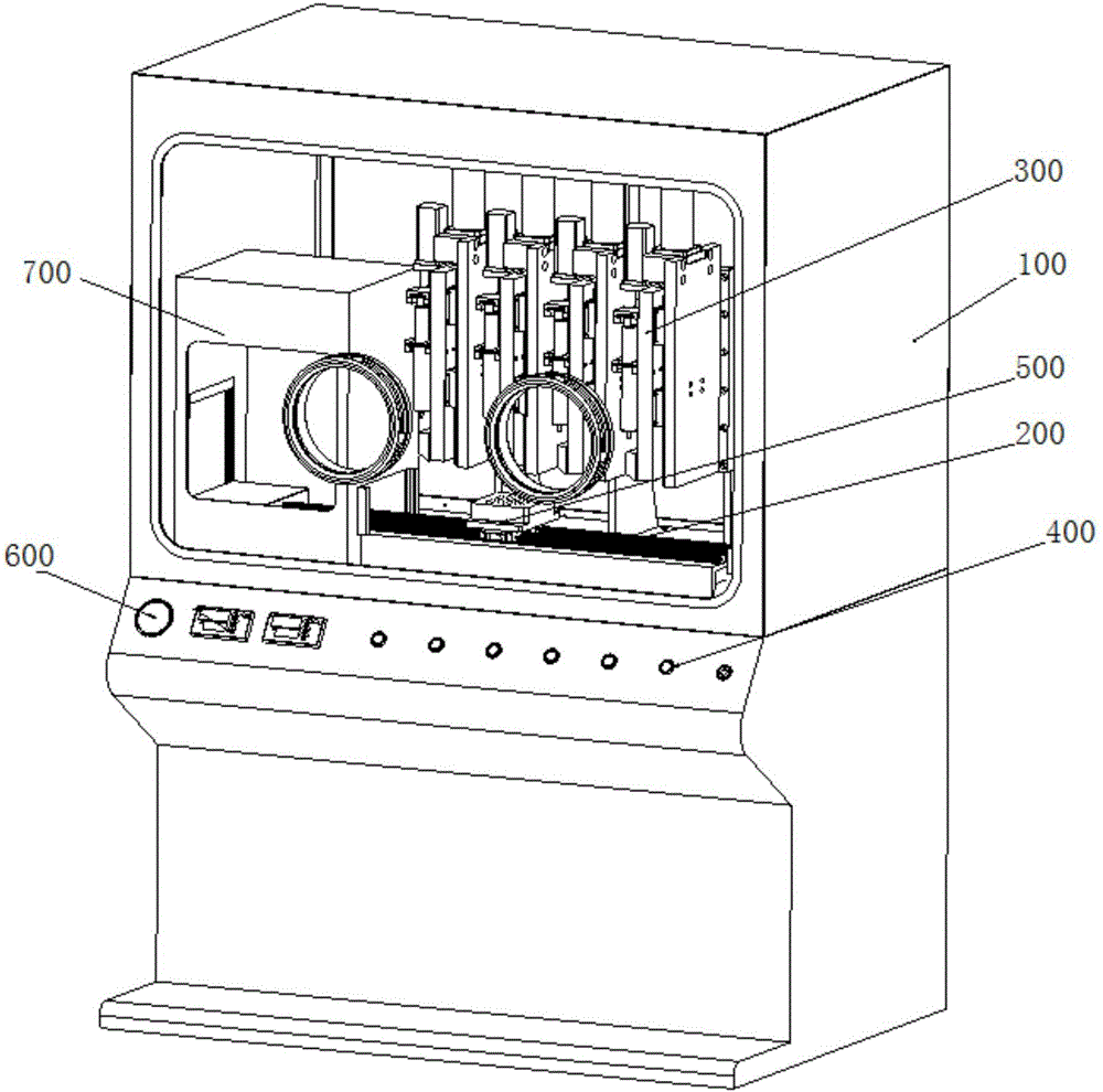
[0049] A formal structure perovskite solar cell is prepared, which includes a transparent conductive substrate, a conductive sublayer, a photoelectric conversion layer and a hole-conducting layer sequentially coated on the transparent conductive substrate. Correspondingly, the present invention includes three push-coating System, according to the printing order, the corresponding coating die number 1, 2, 3.
[0050] The working process of the present invention is as follows: before printing, open the air inlet valve to introduce protective gas into the shell, so as to realize the complete isolation of the printing process from the outside world, and protect the perovskite solar cell from other environmental factors during the printing process; The clean 10cm×10cm transparent conductive substrate is placed on the vacuum adsorption platform, and the movement speed of the vacuum adsorption platform on the moving platform is controlled to be 1~100mm / sec, so that it passes through t...
example 2
[0054] A trans-structured perovskite solar cell is prepared, which comprises a transparent conductive substrate, a hole-conducting layer, a photoelectric conversion layer, a conductive sublayer and an electrode material layer sequentially coated on the transparent conductive substrate. Correspondingly, the present invention includes 4 A bolus coating system, according to the printing order, the corresponding coating die number 1, 2, 3, 4.
[0055] The working process of the present invention is as follows: place the cleaned 10cm×10cm transparent conductive substrate on the vacuum adsorption platform, control the movement speed of the vacuum adsorption platform at 1-100mm / sec, make it pass through the coating die No. 1 at a uniform speed, adjust the The ink extrusion volume of No. 1 coating die is 1-100ul / sec, and the total printing ink volume is controlled to be 1-100ul. Through the above control, the wet film thickness of 1-3 microns can be printed on the transparent conductiv...
example 3
[0060] By replacing the transparent conductive substrate in Example 1 with a flexible transparent conductive substrate (flexible glass substrate or flexible plastic substrate), the printing of flexible formal perovskite solar cells can be realized.
PUM
 Abstract
Description
Claims
Application Information
 - R&D
- Intellectual Property
- Life Sciences
- Materials
- Tech Scout
- Unparalleled Data Quality
- Higher Quality Content
- 60% Fewer Hallucinations
Browse by: Latest US Patents, China's latest patents, Technical Efficacy Thesaurus, Application Domain, Technology Topic, Popular Technical Reports.
© 2025 PatSnap. All rights reserved.Legal|Privacy policy|Modern Slavery Act Transparency Statement|Sitemap|About US| Contact US: help@patsnap.com