
Stackable packaging box

A technology for packaging boxes and boxes, which is applied in the directions of packaging, transportation and packaging, and packaging of fragile items, etc., can solve the problems of breakage of the liquid crystal panel 80, low friction, deformation and eversion of the side walls, etc., and reduce the possibility of fragmentation. , Prevent horizontal shaking, reduce the effect of sidewall eversion

Active Publication Date: 2016-08-24
TCL CHINA STAR OPTOELECTRONICS TECH CO LTD
View PDF6 Cites 8 Cited by
  • Summary
  • Abstract
  • Description
  • Claims
  • Application Information

AI Technical Summary

Problems solved by technology

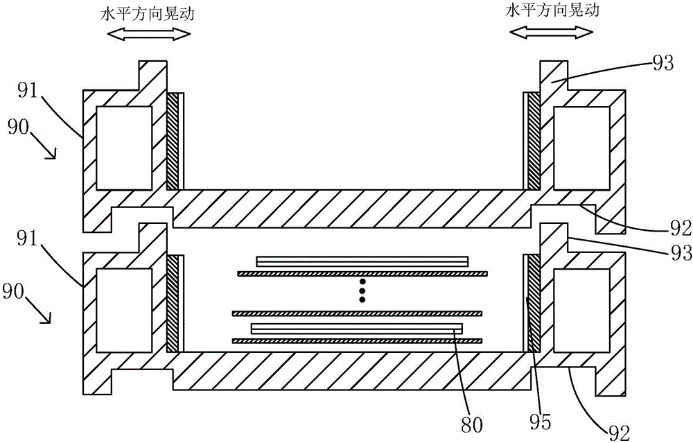
[0005] However, in order to facilitate the packaging operation and reduce the difficulty of the process, a certain assembly gap needs to be reserved for the cooperation between the packaging boxes 90, and the width of the protrusion 93 is usually configured to be smaller than the width of the groove 92. At the same time, due to the packaging box 90 is made of plastic material, its material is relatively hard, and its surface has relatively small frictional force, so the packaging box 90 after stacking is easy to produce horizontal shaking during transportation, resulting in the liquid crystal panel 80 packaged inside the packaging box 90 and the side wall of the packaging box 90 The retaining wall 95 provided on the upper side is impacted in the horizontal direction, causing damage to the liquid crystal panel 80 and other defects.
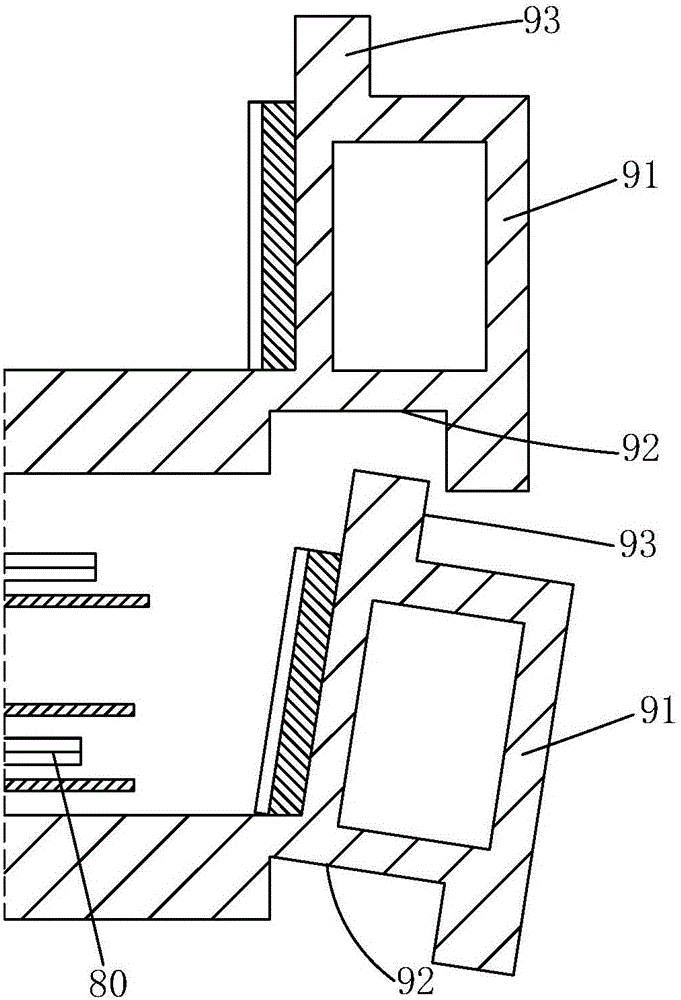
[0006] In addition, if figure 2 As shown, due to the large number of liquid crystal panels 80 loaded in the packaging box 90, the packaging boxes 90 are self-heavy after stacking, and the side walls of the packaging boxes 90 located on the bottom layer are over-pressed, and the side walls will be deformed and turned outwards, and there is a risk of the packaging boxes being stacked upside down.

Method used


Image

  • Stackable packaging box
  • Stackable packaging box
  • Stackable packaging box

Examples


Embodiment Construction

[0035] In order to further illustrate the technical means adopted by the present invention and its effects, the following describes in detail in conjunction with preferred embodiments of the present invention and accompanying drawings.

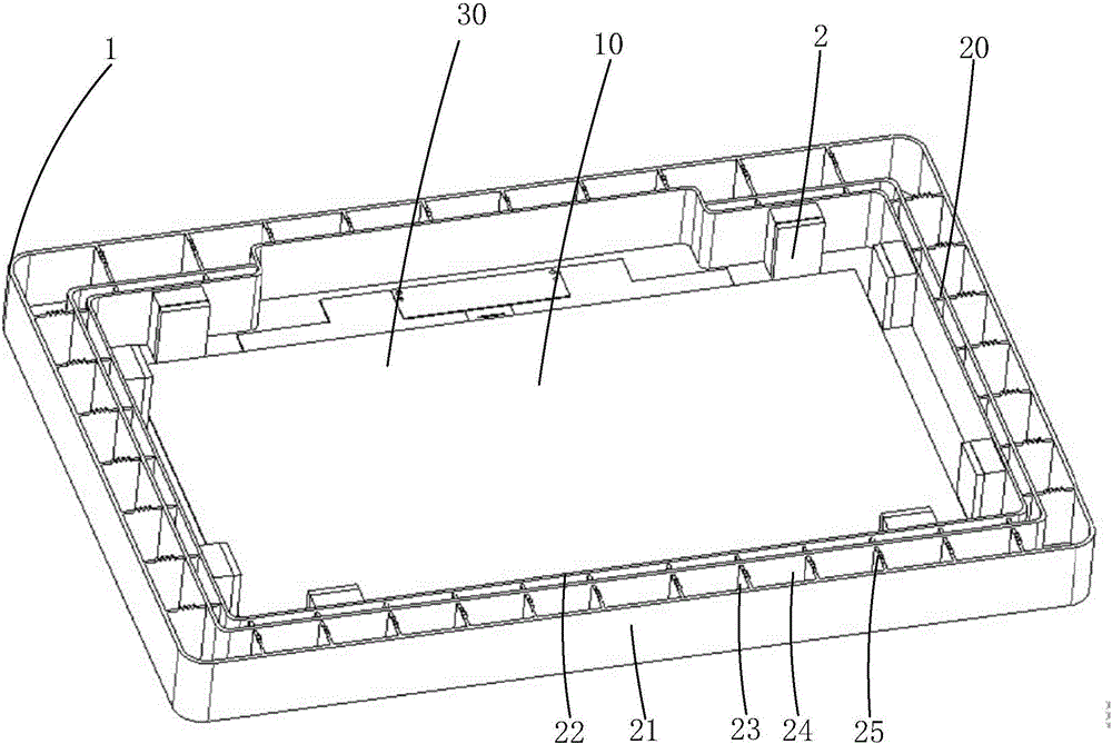
[0036] see Figure 3 to Figure 7 , the present invention provides a stackable packaging box for packaging liquid crystal panels, comprising a box body 1 made of plastic material with an opening on the top surface, and several buffer baffles located in the box body 1 for buffering the liquid crystal panel 2.

[0037] Specifically, the box body 1 includes a bottom plate 10 and a side wall 20 vertically connected to the bottom plate 10 , the bottom plate 10 and the side wall 20 together define a receiving groove 30 for accommodating a liquid crystal panel.

[0038] Specifically, the plurality of buffer baffles 2 are fixed on the inner side of the side wall 20, and the buffer baffles 2 are made of elastic materials. Specifically, as Figure 5-6...


PUM


Abstract

The invention provides a stackable packaging box. Mutually-meshed micro-structures are respectively arranged at the bottom surface of a base plate of a box body and the top surface of the sidewall of the box body, so that when the packaging box is stacked, the base plate of the box body at the upper layer and the sidewall of the box body at the lower layer form close position limitation under the effect of gravity, the stacked packaging box, especially a plastic packaging box is prevented from horizontal jitter generated in a transportation process; therefore, the possibility of damage of a liquid crystal panel inside the packaging box is reduced; meanwhile, the possibility of eversion and reversion of the sidewall of the packaging box can be reduced as well.

Description

technical field [0001] The invention relates to a packing box, in particular to a stackable packing box. Background technique [0002] Liquid crystal panels are important components of electronic products with display functions such as televisions, computers, and mobile phones, and they need to be transported to the assembly or processing workshops of the above electronic products through transport devices. However, whether it is a semi-finished liquid crystal panel (Open Cell) or a finished liquid crystal panel, it needs to be packaged and shipped in a packing box to ensure the safety of the finished liquid crystal panel and its semi-finished product. [0003] Plastic injection boxes, such as High Density Polyethylene (HDPE), have the characteristics of high strength, unbreakable, and reusable, and have been widely used in the packaging of liquid crystal panels. At the same time, because the material of this kind of packaging box is relatively hard and has poor cushioning ...

Claims


Application Information

Patent Timeline
IPC IPC(8): B65D21/032B65D85/48
CPCB65D21/0212B65D85/48
Inventor 岳亮
Owner TCL CHINA STAR OPTOELECTRONICS TECH CO LTD
Learn More