Wet cleaning equipment
A wet cleaning and equipment technology, which is applied in the manufacture of electrical components, circuits, semiconductors/solid-state devices, etc., can solve problems such as high defect density, achieve the effects of reducing defect density, improving product yield, and improving reaction
- Summary
- Abstract
- Description
- Claims
- Application Information
AI Technical Summary
Problems solved by technology
Method used
Image
Examples
Embodiment 1
[0091] This embodiment provides a kind of wet cleaning equipment, comprising:
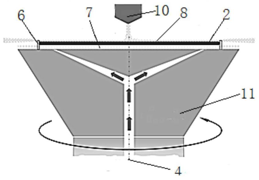
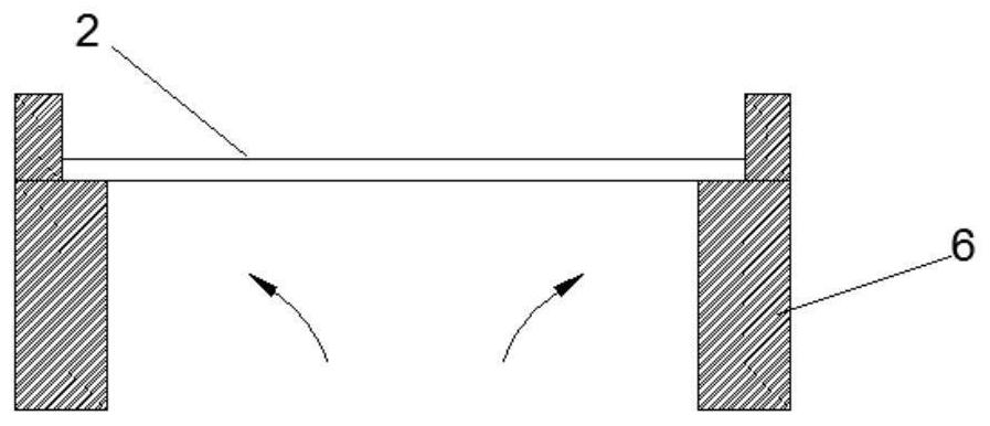
[0092] Rotary table, the surface of the rotary table is provided with an air outlet centered on the central axis of the rotary table, and the rotary table can rotate around the central axis of the rotary table; six pins, the six pins are centered on the central axis of the rotary The upper surface of the table is equidistant from the circumference, and the circular air outlet of the rotary table is set on the inner side of the pins. Multiple pins are used to support the wafer on the rotary table and prevent the wafer from shaking horizontally due to the influence of the air flow; Device components near the wafer edge have increased airflow channels.
[0093] The interior of the turntable is provided with a gas delivery pipeline connected to the gas outlet. The gas outlet is an annular gas outlet with the center of the turntable as the center. The gas is ejected through the gas outlet to form a gas ...
Embodiment 2
[0097] Figure 8a A schematic diagram of a vertical cross-sectional structure of a rotary table according to an embodiment of the present invention, Figure 8b Another structural schematic diagram of a rotary table according to an embodiment of the present invention, Figure 9 A schematic diagram of the gas flow of a rotary table according to an embodiment of the present invention.
[0098] The embodiment provides a rotary table for wet cleaning equipment, the surface of the rotary table is provided with an annular air outlet 1 centered on the central axis of the rotary table, the rotary table can rotate around the central axis of the rotary table, and the interior of the rotary table is provided with The gas delivery pipeline 4 connected to the annular gas outlet 1 , the increased gas flow channel includes a recess 3 arranged on the turntable, and the recess 3 is close to the edge of the wafer 2 .
[0099] like Figure 8a As shown, when the depression 3 is an annular groov...
Embodiment 3
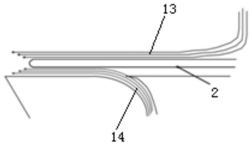
[0103] Figure 4a A schematic diagram of the pin structure of a single through hole according to an embodiment of the present invention, Figure 4b A cross-sectional view of a pin of a single through hole according to an embodiment of the present invention, Figure 5a A schematic diagram of a pin structure of a double through hole according to an embodiment of the present invention, Figure 5b According to an embodiment of the present invention, a cross-sectional view of a pin of a double through hole, Figure 6a A schematic diagram of the pin structure of the frustoconical through hole according to an embodiment of the present invention, Figure 6b A cross-sectional view of pins of a frustum-shaped through hole according to an embodiment of the present invention, Figure 7a A schematic diagram of the gas flow before the gas acts on the wafer according to an embodiment of the present invention, Figure 7b A schematic diagram of gas flow after gas is applied to a wafer acco...
PUM
 Abstract
Description
Claims
Application Information
 - R&D
- Intellectual Property
- Life Sciences
- Materials
- Tech Scout
- Unparalleled Data Quality
- Higher Quality Content
- 60% Fewer Hallucinations
Browse by: Latest US Patents, China's latest patents, Technical Efficacy Thesaurus, Application Domain, Technology Topic, Popular Technical Reports.
© 2025 PatSnap. All rights reserved.Legal|Privacy policy|Modern Slavery Act Transparency Statement|Sitemap|About US| Contact US: help@patsnap.com


