Displacement frame girder bridge inspection vehicle

A frame and displacement technology, applied in bridges, bridge parts, bridge construction, etc., can solve the problems of limited railway rail transit bridge lines, increased bridge construction costs, equipment flexibility restrictions, etc., to achieve distributed load distribution, safety protection design. The effect of humanization, increased convenience and safety

Inactive Publication Date: 2018-01-23
北京联桥智能装备技术有限公司
View PDF6 Cites 0 Cited by
  • Summary
  • Abstract
  • Description
  • Claims
  • Application Information

AI Technical Summary

Problems solved by technology

Since the optimal design of high-speed railway bridges in my country in 2008, considering the safety of high-speed trains, people are not allowed to pass on the bridge and other equipment when the train is passing, and the catenary pillars are set on the outside of the sidewalk. These measures have improved the closure and safety of high-speed railways. At the same time, it is extremely inconvenient to use sidewalk inspection vehicles on high-speed railway bridge decks
[0005] The pre-buried track under the bridge walking inspection vehicle adopts the track method, and the inspection vehicle track is placed under the bridge deck. The embedded parts for fixing the track need to be pre-embedded on the bridge web when the beam is made. This kind of inspection vehicle is used This method requires a large number of embedded parts and tracks, which is a large investment and reusable method, but this method increases a lot of bridge construction costs, and the inspection of railway track traffic bridge lines is limited, and the flexibility of equipment is severely limited

Method used


Image

  • Displacement frame girder bridge inspection vehicle
  • Displacement frame girder bridge inspection vehicle
  • Displacement frame girder bridge inspection vehicle

Examples


Embodiment Construction

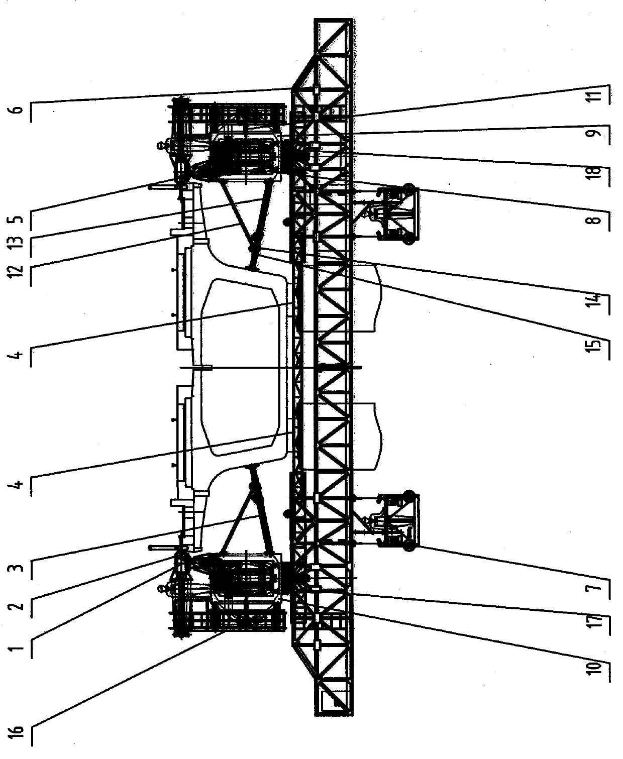
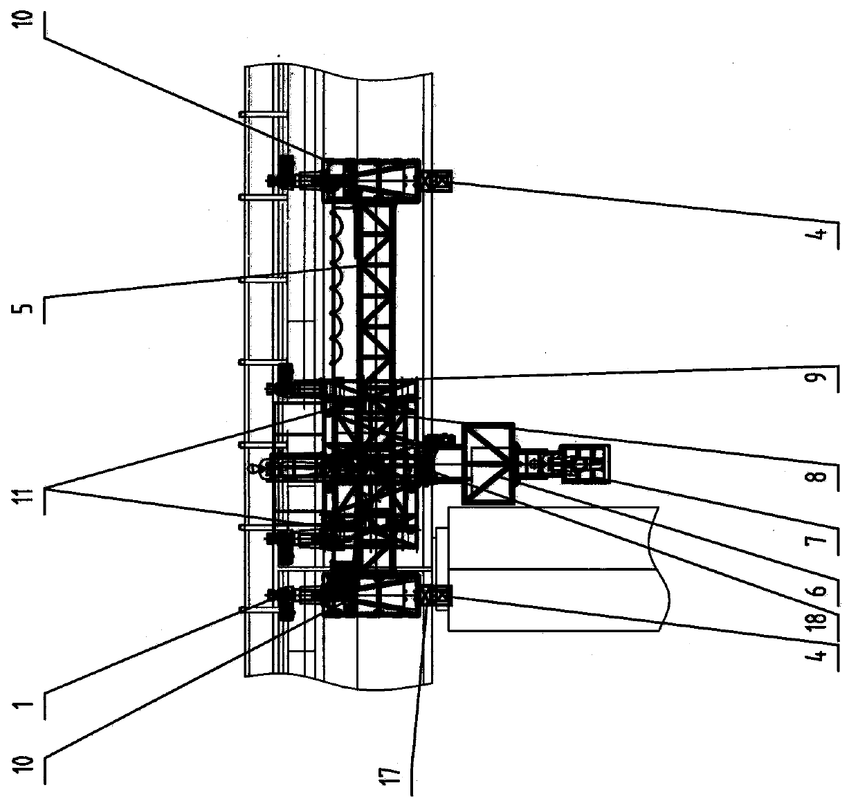
[0021] Such as figure 1 , figure 2 , image 3 As shown, the displacement frame beam type bridge inspection vehicle of the present invention includes: bridge deck self-locking hook palm 1, anti-collision roller 2, triangular outrigger 3, cross-link beam 4, guide beam 5, rotating platform 6, hanging basket 7, main Frame inner frame 8, main frame outer frame 9, fixed truss structure 10, electric push rod 11, fixed-length outrigger 12, telescopic leg 13, slider 14, limit device 15, steel ladder and guardrail 16, cross-link Beam lifting frame 17, rotating platform lifting frame 18, main frame outer frame 9 is connected with rotating platform 6, constitutes the passageway of detection and maintenance bridge.

[0022] Such as figure 1 As shown in the present invention, the displacement frame beam-type bridge inspection vehicle, the self-locking hook palm 1 of the bridge deck can be automatically fixed and locked or unlocked on the bridge edge of the bridge deck, and the self-lock...


PUM


Abstract

The invention relates to equipment for detection and maintenance of high-speed railways and track viaducts. Its purpose is to provide detection and maintenance methods for high-speed railways and track viaducts. The displacement frame girder type bridge inspection vehicle of the present invention includes bridge deck self-locking hook palms, triangular outriggers, cross-link beams, guide beams, cross-link beam lifting frames, rotating platforms, rotating platform lifting frames, main frame inner and outer frames, fixed truss structures, etc. , the outer frame of the main frame and the lifting frame of the rotating platform are connected with the rotating platform to form a channel for inspection and maintenance of the bridge. There are at least two groups of connecting beams or rotating platforms that are connected. The two connecting beams can be lifted up and down driven by their respective horizontal connecting beam lifting frames, and the rotating platform can be lifted up and down driven by their rotating platform lifting frames. This equipment can adapt to different Inspection and maintenance of simply supported concrete girder bridges and concrete continuous girder bridges of varying heights.

Description

technical field [0001] The invention relates to detection and maintenance equipment for high-speed railways and track viaducts, in particular to a displacement frame girder bridge inspection vehicle. Background technique [0002] At present, there are three main types of bridge inspection vehicles that have been put into use by railways and light rails in various countries: rail-type, sidewalk-type and under-bridge pre-buried track-type. [0003] The rail-type bridge inspection vehicle takes the main track as the track, has fast driving speed, stable structure, relatively mature technology, and has been applied both at home and abroad. Such as the Austrian PALFINGER PB4 railway bridge inspection vehicle and the Golden Eagle hanging basket bridge inspection vehicle used in my country's Qinghai-Tibet Railway. This type of rail-type bridge inspection vehicle needs to occupy the operating track, so it can only be carried out under the condition of the transportation skylight, an...

Claims


Application Information

Patent Timeline
Patent Type & Authority Patents(China)
IPC IPC(8): E01D19/10
Inventor 刘亚滨南彭川曹学伟贾艳歧
Owner 北京联桥智能装备技术有限公司
Why Eureka
Try Eureka