Connection mechanism between tubes and tube bases of a heat exchanger and method for producing the connection mechanism

A connection mechanism and heat exchanger technology, applied in heat exchange equipment, heat exchanger shells, lighting and heating equipment, etc., can solve the problems of expensive film and troublesome welding, and achieve the effect of eliminating deformation and achieving shape stability.

Active Publication Date: 2018-03-30
WALLSTEIN ING
View PDF7 Cites 0 Cited by
  • Summary
  • Abstract
  • Description
  • Claims
  • Application Information

AI Technical Summary

Problems solved by technology

But on the other hand there is still the problem of expensive and cumbersome welding between the tube and the film covering the bottom of the tube

Method used


Image

  • Connection mechanism between tubes and tube bases of a heat exchanger and method for producing the connection mechanism
  • Connection mechanism between tubes and tube bases of a heat exchanger and method for producing the connection mechanism
  • Connection mechanism between tubes and tube bases of a heat exchanger and method for producing the connection mechanism

Examples


Embodiment Construction

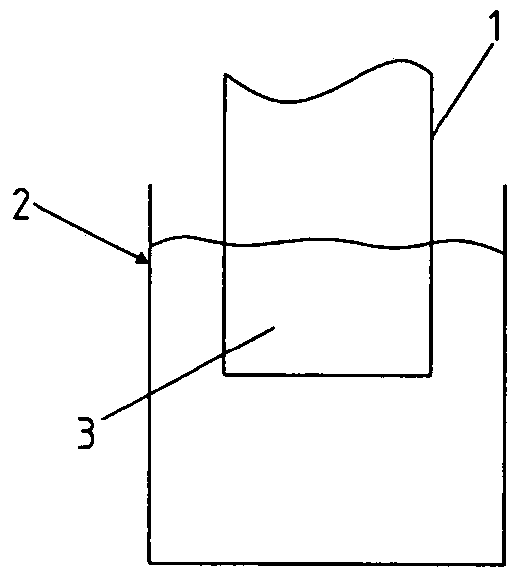
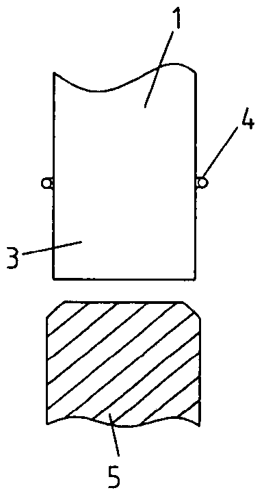
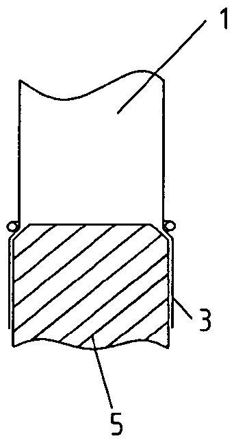
[0047] figure 1 A situation in which a tube 1 made of fluoropolymer plastic is immersed in a salt solution bath 2 is shown. The end section of the tube 1 to be heated should be heated to the softening temperature. If this temperature is reached, the tube 1 is removed from the bath 2. Immediately afterwards, the blocking body 4 in the form of a ring is put on the tube 1. The diameter of the blocking body 4 is only slightly larger than the diameter of the tube 1. At present, the heated end section 3 in a state capable of plastic deformation is positioned on the mandrel 5, which is inserted into the end section 3 so that the end section 3 is expanded in the radial direction ( figure 2 with 3 ).

[0048] Next, the radially enlarged end section 3 is rolled and guided on the blocking body, so that the blocking body is located in a loop 6 which is formed by the rolled end section. The previously heated area cools down and clings to the outside of the tube 1 in a manner not shown in...


PUM


Abstract

The invention relates to a connection between tubes (1) and tube bases (8) of a heat exchanger and a method for producing the same. Therein, the pipe (1) has an end section (3), which is inserted into an opening (9) in the pipe base (8), and the connection means comprises a sleeve (16), which is arranged in the tube (1) and presses the end section (3) sealingly radially outwards against the wall (10) of the opening (9), so that the tube (1) is held clampingly in in the opening (9). The end section (3) is double-walled by rolling over the tube (1) and has a loop (6) on the end side, wherein the connecting means comprises a blocking body (4) which Arranged in the loop (6) such that the loop (6) forms a flange (7) with an outer diameter (AD) which is at least partially larger than the opening (9). The connection mechanism is airtight.

Description

Technical field [0001] The present invention relates to a connecting mechanism between a tube and a tube bottom of a heat exchanger and a method for manufacturing the connecting mechanism. Background technique [0002] A gas-gas-heat exchanger operating in a cross-flow method is known. Such heat exchangers are used, for example, for heat recovery in flue gas systems. The raw gas delivered to the flue gas desulfurization device leaves the flue gas desulfurization device to become a clean gas with a lower temperature. The clean gas is reheated by the thermal energy of the raw gas in the heat exchanger, so that the clean gas maintains a prescribed temperature before entering the flue. Because the clean gas may cause the condensation of pollutants when the temperature drops below the dew point, the heat exchanger can be made of tubes and liners made of fluoroplastics. A tube made of fluoroplastics is suspended in the tube bottom (Rohrboden, tube sheet). In this case, the tube is ...

Claims


Application Information

Patent Timeline
Patent Type & Authority Patents(China)
IPC IPC(8): F28F9/16
CPCF28F9/165F28F21/062
Inventor S·里德尔W·恩格尔金
Owner WALLSTEIN ING
Why Eureka
Try Eureka