Device for comparing test performance of force measuring locking anchor pipes of tunnel and test method

A technology for locking foot anchors and testing performance, which can be used in measurement devices, force measurement by measuring the change of optical properties of materials when they are stressed, force/torque/work measurement instrument calibration/testing, etc., which can solve the problem of national resources. Waste, tunnel construction buried, safety hazards and other issues, to achieve the effect of good theoretical basis and support, simple installation method, effective feasibility

Active Publication Date: 2016-08-24
CHANGAN UNIV
View PDF6 Cites 10 Cited by
  • Summary
  • Abstract
  • Description
  • Claims
  • Application Information

AI Technical Summary

Problems solved by technology

However, there are still relatively few studies on the mechanical characteristics and mechanism of the lock-foot anchor pipe, and most of them are analyzed through engineering experience analogy and numerical simulation. Therefore, it is imperative to study the mechanical properties and stress mechanism of the lock foot anchor pipe
[0003] The existing monitoring methods for the force characteristics of the lock-foot anchor tube, such as the force-measuring lock-foot anchor tube with resistance strain gauges, have many shortcomings when they are applied to the construction site for long-term monitoring. The test data in the construction environment is difficult to maintain long-term stability, susceptible to electromagnetic interference, the test data is inconsistent, the error is large, and it is difficult to achieve long-term monitoring
[0004] However, it is difficult to judge the feasibility of the test and the accuracy of the test data before applying the fiber grating sensing technology to the test of the mechanical characteristics of the tunnel lock foot anchor pipe. It can be seen that it is important to find a comparative method to verify it. sex

Method used


Image

  • Device for comparing test performance of force measuring locking anchor pipes of tunnel and test method
  • Device for comparing test performance of force measuring locking anchor pipes of tunnel and test method
  • Device for comparing test performance of force measuring locking anchor pipes of tunnel and test method

Examples


Embodiment

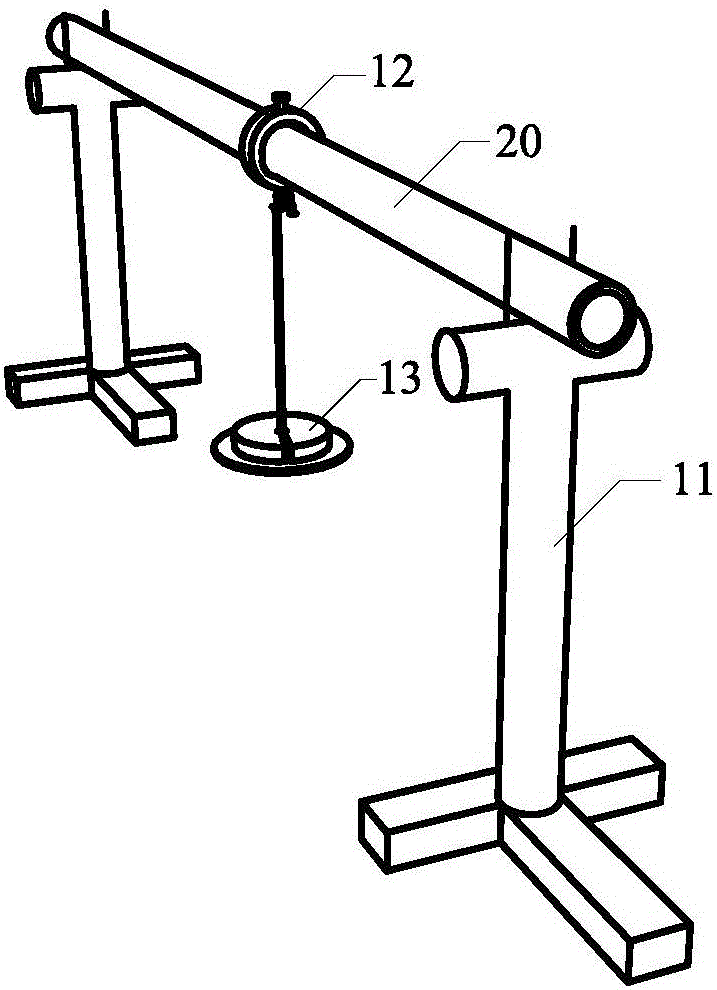
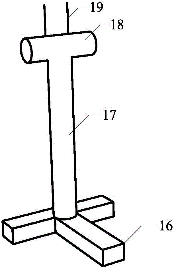
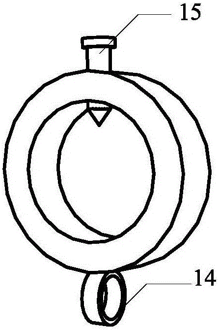
[0068] The test was carried out in the Key Laboratory of Bridges and Tunnels, Chang'an University, Shaanxi Province. The welded steel support frame was used as the hinge support at both ends of the simply supported beam, and the force-measuring lock-foot anchor tube was used as the beam part of the simply supported beam. Weights are stacked just below the loading ring to simulate the concentrated load experienced by a simply supported beam. The main purpose of the test is to compare the test performance of the force-measuring lock-foot anchor tube with embedded bare fiber gratings and the force-measuring lock-foot anchor tube with resistance strain gauges under load. The test performance of the lock-foot anchor tube is compared, and the force characteristics of the force-measuring lock-foot anchor tube with embedded fiber gratings are analyzed. The data acquisition system used in this test electrical measurement method is the TST3821E wireless telemetry static strain gauge, an...


PUM

PropertyMeasurementUnit
electrical resistanceaaaaaaaaaa
gauge factoraaaaaaaaaa

Abstract

The invention relates to a device for comparing the test performance of the force measuring locking anchor pipes of a tunnel and a test method. The device is convenient to install and easy to operate. The device can be used for fast verifying the test performance of the force measuring locking anchor pipe with an optical fiber grating buried therein and can be applied to the detection of the test performance of force measuring devices such as tube type force measuring devices and rod type force measuring devices. According to the technical schemes of the invention, the device of the invention includes a force measuring locking anchor pipe with an optical fiber grating buried therein, a force measuring locking anchor pipe with resistance strain gauges pasted therein, a loading ring and a supporting frame, wherein the loading ring and the supporting frame are applied to comparison. The two kinds of force measuring locking anchor pipes are arranged on the supporting frame, so that step-by-step loading tests are carried out, and the measurement results of the tests of the force measuring locking anchor pipes are compared with theoretical values, and therefore, the test performance of the two kinds of the force measuring locking anchor pipes can be analyzed and evaluated.

Description

technical field [0001] The invention relates to a device and a test method for comparing the test performance of a tunnel force-measuring lock foot anchor pipe. Background technique [0002] Since entering the 21st century, my country's social economy and scientific and technological level have been continuously improved. With the proposal of the two major economic belt strategies of "One Belt, One Road" and "Maritime Silk Road", the construction of bridges, tunnels, dams, highways and other major transportation projects Construction has achieved rapid development. As far as the construction of tunnels is concerned, not only the number and scale of tunnels have been expanded, but also the excavation sections have been increasing, and more and more difficulties have been encountered. For tunnel construction under complex geological conditions, the problems it faces are increasing. For example, in the excavation process of a tunnel with weak surrounding rock, due to the poor ...

Claims


Application Information

Patent Timeline
Patent Type & Authority Applications(China)
IPC IPC(8): G01L1/24G01L1/22G01L25/00
CPCG01L1/22G01L1/242G01L25/00
Inventor 陈建勋罗彦斌李栋刁鹏升翟宇辉
Owner CHANGAN UNIV
Why Eureka
Try Eureka