
Hypersonic speed wind-tunnel nozzle outlet segment water cooling device

A technology of nozzle exit and hypersonic speed, which is applied in the direction of measuring devices, instruments, aerodynamic tests, etc., can solve the problems of electrical equipment safety hazards, equipment corrosion in the test section, and easy leakage of cooling water, etc., to achieve good cooling effect and avoid Local dry burning and low processing cost

Inactive Publication Date: 2016-08-24
INST OF HIGH SPEED AERODYNAMICS OF CHINA AERODYNAMICS RES & DEV CENT
View PDF8 Cites 29 Cited by
  • Summary
  • Abstract
  • Description
  • Claims
  • Application Information

AI Technical Summary

Problems solved by technology

At present, some hypersonic wind tunnel nozzle outlet sections do not have a cooling device; some hypersonic wind tunnel nozzle nozzles are welded on the nozzle outlet section and the inner wall of the test section, and connected with pipes to make a return pipe to make the cooling water A loop is formed to achieve high-efficiency cooling. However, when replacing the nozzle, the return pipe connected to the test section must be disassembled. The replacement efficiency is low, and the cooling water is easy to leak into the test section, causing corrosion of the internal equipment of the test section and electrical appliances. Equipment security risks

Method used


Image

  • Hypersonic speed wind-tunnel nozzle outlet segment water cooling device
  • Hypersonic speed wind-tunnel nozzle outlet segment water cooling device
  • Hypersonic speed wind-tunnel nozzle outlet segment water cooling device

Examples


Embodiment Construction

[0027] The present invention will be described in detail below in conjunction with the accompanying drawings.

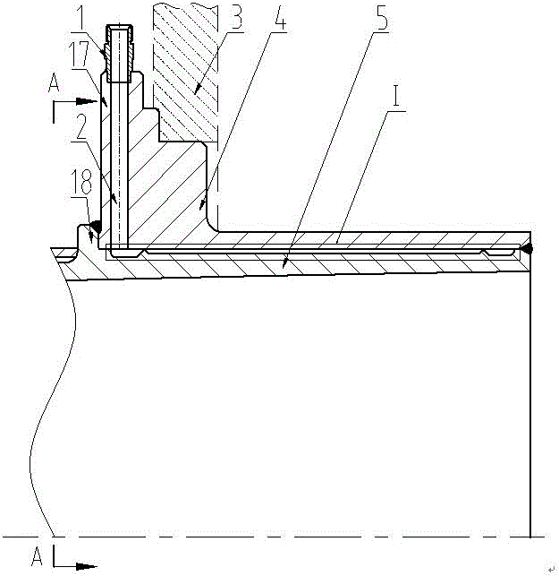
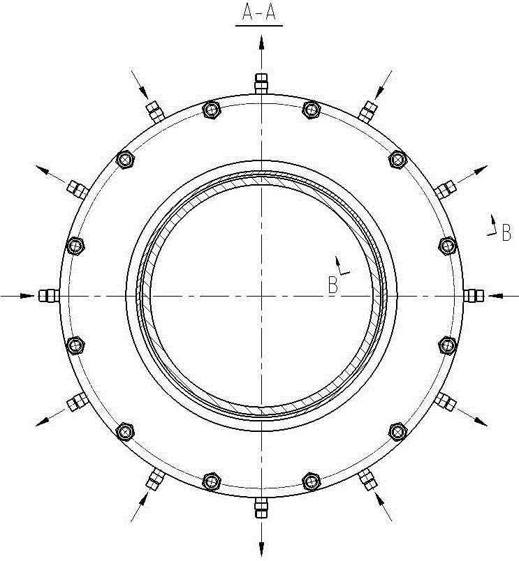
[0028] Such as figure 1 As shown, the exterior of the outer casing 4 is provided with a positioning and sealing end surface, which is docked with the entrance side wall plate 3 of the test section of the wind tunnel for positioning and sealing. The outer casing 4 is wrapped on the inner casing 5, and is sealed and connected with the annular seams on both sides of the inner casing 5 by full welding. Between the outer casing 4 and the inner casing 5 is an interlayer for the circulation of cooling water, and the interlayer is divided into two parts by the water dividing rib 6 and the blocking block 7 welded on the inner casing 5 ncooling unit. There is a flange I17 on the outer shell 4, and there is a water hole 2 along the radial direction of the flange I. The outer side of the water hole 2 is welded with a water joint 1, and the water joint 1 is connected to an ext...


PUM


Abstract

A hypersonic speed wind-tunnel nozzle outlet segment water cooling device provided by the present invention comprises a water joint, an outer shell, an inner shell, a block and a water bar. The cooling water of the water cooling device flows in an interlayer between the outer shell and the inner shell of a nozzle outlet segment directly from the water joint outside a wind tunnel test segment, returns at the tail end of the nozzle outlet segment, and flows out from the water joint, so that the cooling water forms the circulation inside the nozzle outlet segment. According to the present invention, a water pipe does not need to be connected between the tail end of a wind tunnel nozzle segment and the wind tunnel test segment to form a water return pipe, so that the water cooling device is not correlated with the wind tunnel test segment. A wind tunnel nozzle can be replaced by just disengaging the wind tunnel nozzle from the test segment directly without needing to disassemble the water return pipe, so that the water cooling device has a very high replacement operation efficiency, and the situation that the cooling water leaks to the test segment when the wind tunnel nozzle is replaced, is avoided. Meanwhile, a cooling unit which is easy to process and is used for restraining the flow of the cooling water is arranged in the interlayer, so that the cooling water flows in the interlayer more evenly, and the nozzle outlet segment can be cooled very well.

Description

technical field [0001] The invention belongs to the technical field of conventional hypersonic wind tunnel tests, and in particular relates to a water cooling device for the exit section of a hypersonic wind tunnel nozzle. Background technique [0002] Conventional hypersonic wind tunnel nozzles are Laval nozzles, which are formally divided into constriction section, throat section, and expansion section, and structurally divided into four parts: entrance section, throat section, middle expansion section, and exit section. The exit section of the nozzle needs to be inserted into the hypersonic wind tunnel test section. During the test, the flow from the wind tunnel flows through the nozzle and flows into the test section. The total temperature of the flow from the wind tunnel is relatively high, sometimes exceeding 800°C. The test time is usually above 60s. Some tests can last up to 240s. The high-temperature airflow has a significant heating effect on the nozzle. In the abs...

Claims


Application Information

Patent Timeline
IPC IPC(8): G01M9/02
CPCG01M9/02
Inventor 叶成周晓刚白本奇秦天超胥继斌杨海滨董宾尹疆黄昊宇
Owner INST OF HIGH SPEED AERODYNAMICS OF CHINA AERODYNAMICS RES & DEV CENT
Learn More