
Method and device for calibrating eclectic arc discharge energy correction factor

A correction factor and arc discharge technology, which is applied to measuring devices, measuring electrical variables, instruments, etc., can solve problems such as explosion, unsafe direct test method, and inability to obtain quantitative data, and achieve high accuracy and convenient use and setup. Effect

Active Publication Date: 2016-08-24
BEIHANG UNIV
View PDF5 Cites 4 Cited by
  • Summary
  • Abstract
  • Description
  • Claims
  • Application Information

AI Technical Summary

Problems solved by technology

[0005] However, the direct test method also has some insurmountable shortcomings: First, the direct test method is relatively unsafe, and the combustible gas in a confined space is not easy to control after being ignited, and even has the risk of explosion; the direct test method can only carry out qualitative analysis , the test results are only valid for the test conditions, so quantitative data cannot be obtained, so the test data cannot be used to evaluate the results under other test conditions; because the main parameters of the discharge phenomenon cannot be recorded during the test, it is impossible to monitor and analyze them in real time and record test data, it is impossible to provide a reference for system improvement

Method used


Image

  • Method and device for calibrating eclectic arc discharge energy correction factor
  • Method and device for calibrating eclectic arc discharge energy correction factor
  • Method and device for calibrating eclectic arc discharge energy correction factor

Examples


Embodiment Construction

[0026] The present invention will be described in detail below in conjunction with the accompanying drawings and embodiments.

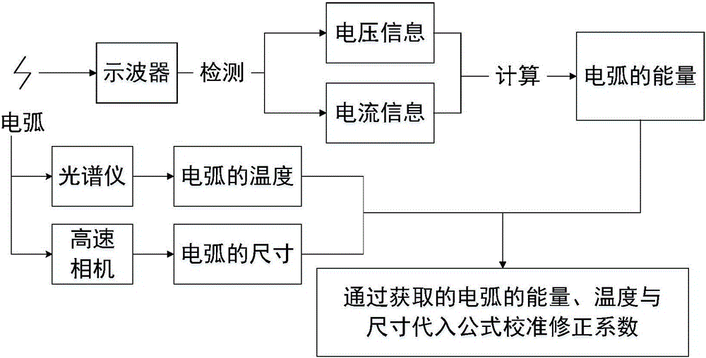
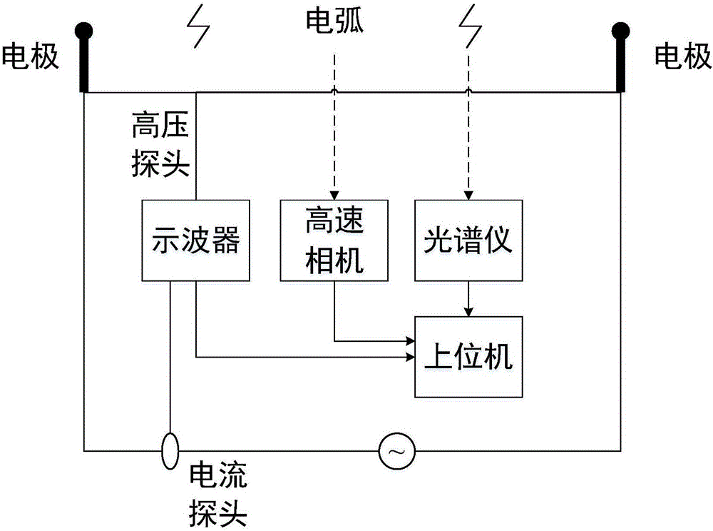
[0027] Such as figure 1 As shown, the discharge energy of the arc can be measured by an oscilloscope. The arc generated by gas discharge has obvious voltage and current characteristics. The voltage curve of the arc during the discharge period can be measured by using the high-voltage probe of the oscilloscope, and the current curve of the circuit during the discharge period can be measured by using the current probe, and the measured curve is stored and recorded. The relationship between energy, voltage and current can be accurately calculated to obtain the discharge energy of the arc. Arc discharge energy calculation formula: The temperature of the arc can be measured by a spectrometer. The gas discharge forms an arc with a distinctly bright light and releases corresponding spectral information. The spectral information of the arc can be collect...


PUM


Abstract

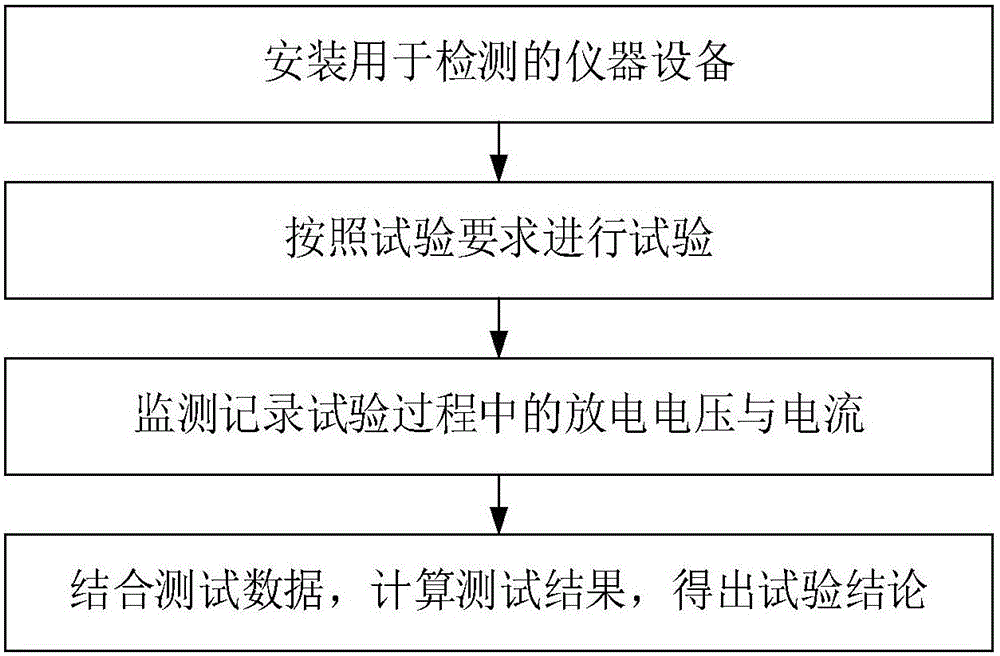
The invention relates to a method and a device for calibrating an eclectic arc discharge energy correction factor. A formula of eclectic arc discharge energy is given according to a semi-empirical formula of minimum ignition energy; energy generated in the electric arc discharge process is calculated according to a relation that the voltage and the current of a gas discharge electric arc change along with time, and finally, in combination with the temperate of the eclectic arc obtained by measurement, the arc length and the radius, the value of the correction factor in the formula is calibrated. The method comprises the following steps: (1) measuring the voltage and current information of the gas discharge electric arc; (2) obtaining the energy generated in the discharge process through an integral of a product of the voltage and the current on a time axis by adopting a mathematical method; (3) measuring the spectral information of the electric arc to obtain the temperature of the electric arc; (4) measuring the size information of the electric arc, wherein the size information comprises length and radius; (5) substituting into the calibration formula of the discharge energy E of the electric arc according to the energy obtained in the step (2), the temperature obtained in the step (3) and the size information obtained in the step (4) to obtain the value of the correction factor K1. The method provided by the invention is convenient to configure and flexible to operate and can quantifiably measure and calibrate the correction factor in the electric arc discharge energy formula.

Description

technical field [0001] The invention relates to a calibration method and a calibration device for an arc discharge energy correction coefficient, in particular to a method for calibrating a correction coefficient in a gas discharge energy formula by indirect measurement of energy, temperature and size information obtained in a strong electromagnetic environment, which belongs to electromagnetic compatibility testing technology field. Background technique [0002] When the electric field in the air is strong enough, the gas molecules will be ionized to form plasma, and a short discharge current will be generated to consume or neutralize the charges, emit light and heat, and produce sound. The spark discharge generally lasts for a short time, and the required electric field strength is very high. Such a field strength generally exists between the tips of two conductive metal bodies, so it is also called tip discharge. [0003] The strong electromagnetic field environment can ...

Claims


Application Information

Patent Timeline
Patent Type & Authority Applications(China)
IPC IPC(8): G01R35/04
CPCG01R35/04
Inventor 戴飞冯骁尧符新凯王顺鑫
Owner BEIHANG UNIV
Learn More