
Bender speed planning method and device

A technology of speed planning and bending machine, applied in the field of bending machine, can solve the problem of prolonging the processing time of board inspection

Active Publication Date: 2016-08-24
GUANGDONG INST OF INTELLIGENT MFG
View PDF8 Cites 5 Cited by
  • Summary
  • Abstract
  • Description
  • Claims
  • Application Information

AI Technical Summary

Problems solved by technology

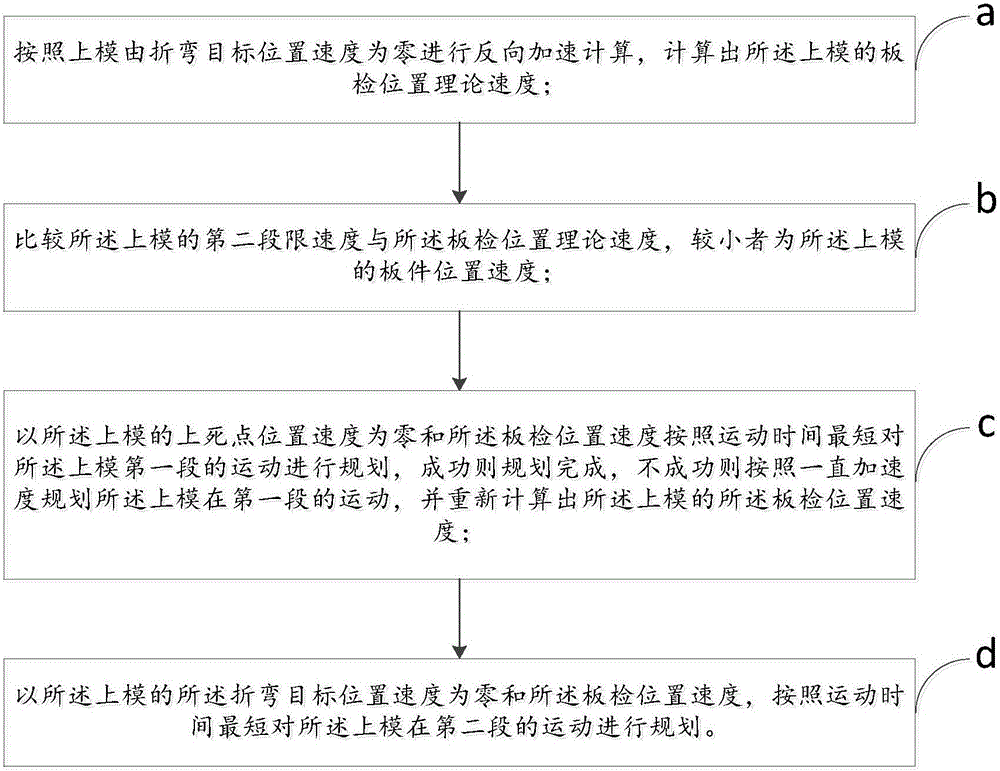
[0006] The purpose of the present invention is to provide a bending machine speed planning method and device to overcome the above-mentioned technical defects, and to solve the problem of determining the data through common sense or experience, so that the movement of the first and second segments of the upper mold does not reach the theoretical level. The shortest time on the board greatly prolongs the processing time for board inspection

Method used


Image

  • Bender speed planning method and device
  • Bender speed planning method and device
  • Bender speed planning method and device

Examples


Embodiment 1

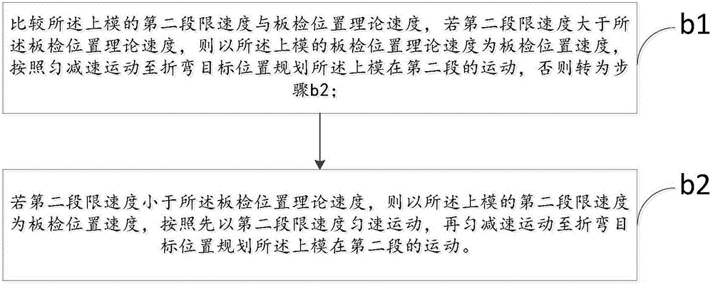
[0070] As mentioned above, the speed planning method of the bending machine, the difference of this embodiment is that, as figure 2 As shown in the flow chart of step b in the bending machine speed planning method of the present invention, said step b includes:

[0071] Step b1, comparing the second speed limit of the upper mold with the theoretical speed of the board inspection position, if the second speed limit is greater than the theoretical speed of the board inspection position, then use the theoretical speed of the board inspection position of the upper die as the board Check the position and speed, and plan the movement of the upper mold in the second section according to the uniform deceleration movement to the bending target position, otherwise go to step b2;

[0072] The calculation formula of uniform motion motion time is:

[0073] t 2 = 2 S ...

Embodiment 2

[0082] As mentioned above, the speed planning method of the bending machine, the difference of this embodiment is that in the step b, the calculation formula of the board inspection position speed is:

[0083] v 1 = ( 1 + v L 2 - v 11 | v 11 - v L 2 | ) v 11 2 + ( 1 + ...

Embodiment 3

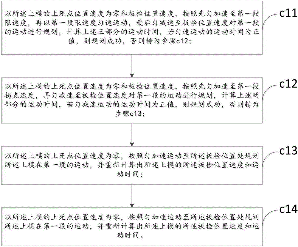
[0088] As mentioned above, the speed planning method of the bending machine, the difference of this embodiment is that, as image 3 The process flow of step c in the bending machine speed planning method of the present invention Figure 1 As shown, the step c includes:

[0089] Step c11, with the speed at the upper dead center position of the upper die being zero and the speed at the board inspection position, first uniformly accelerate to the first speed limit, then move at a uniform speed at the first speed limit, and finally decelerate uniformly to the board inspection position Speed ​​plans the movement of the first segment, and calculates the movement time of the above three parts. If the movement time of the uniform movement is positive, the planning is successful, otherwise go to step c12;

[0090] The calculation formula of the uniform motion time is:

[0091] t 12 = 2 a ...


PUM


Abstract

A bender speed planning method and device are disclosed. The method comprises the following steps: in step a, a theoretical board inspection position speed of an upper mold is calculated; in step b, a second segment limit speed of the upper mold is compared with the theoretical board inspection position speed, a lower one is board inspection position speed of the upper mold; in step c, a dead centre position speed is zero and the board inspection position speed, first segment movement of the upper mold is planned based on a minimal time principle, planning is finished when the planning succeed, otherwise the board inspection position speed is recalculated; in step d, a bending object position speed of the upper mold is zero and the board inspection position speed, and second segment movement of the upper mold is planned based on a minimal movement time principle; the device comprises a calculation module, a comparison module, a first segment planning module and a second segment planning module that are orderly connected. Thus, after speed planning is done, a pressing plate drives the upper mold to move as planned, movement time can be shortened, and bending efficiency can be improved.

Description

technical field [0001] The invention relates to the technical field of bending machines, in particular to a speed planning method and device for a bending machine. Background technique [0002] The bending machine is a machine that can bend thin plates. Due to the use of electromagnetic force clamping, the pressing plate can be made into various workpiece requirements, and it can process the plate inspection with side walls, and the operation is also very simple. . The bending machine is divided into manual bending machine, hydraulic bending machine and CNC bending machine. [0003] The automatic bending process of the CNC bending machine is divided into two sections: the upper mold of the first section moves from the top dead center to the plate inspection position at high speed, and the upper mold of the second section moves from the plate inspection position to the bending target position at a low speed. CNC bending machines often process multiple same or different boar...

Claims


Application Information

Patent Timeline
Patent Type & Authority Applications(China)
IPC IPC(8): G05B19/416B21C51/00
CPCB21C51/00G05B19/4166G05B2219/34169
Inventor 孙克争周雪峰赫亮李凯格程韬波
Owner GUANGDONG INST OF INTELLIGENT MFG
Learn More