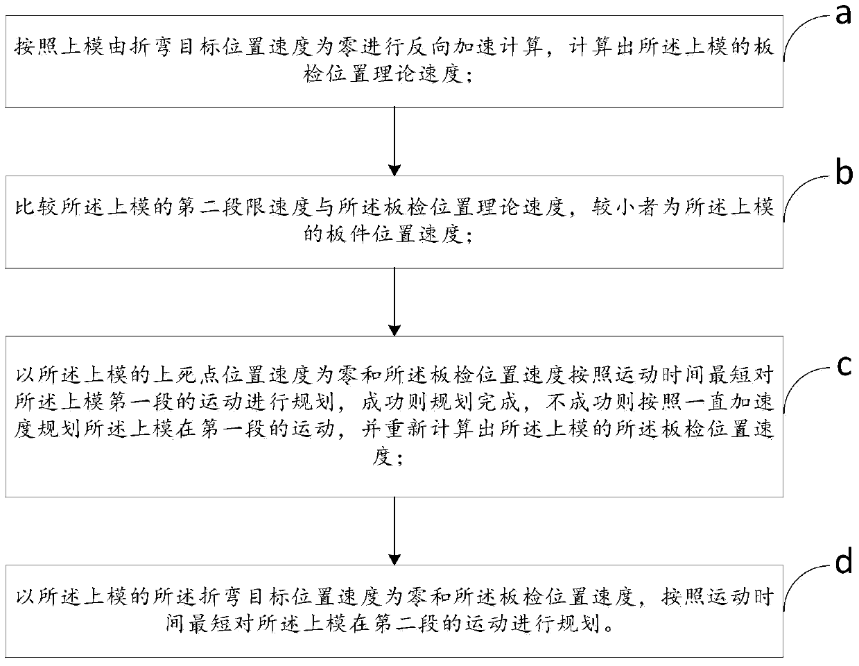
A method and device for speed planning of a bending machine
A speed planning and bending machine technology, applied in the field of bending machines, can solve problems such as prolonging the processing time of plate inspection, achieve excellent bending effect, facilitate calculation, and improve bending efficiency.
- Summary
- Abstract
- Description
- Claims
- Application Information
AI Technical Summary
Problems solved by technology
Method used
Image
Examples
Embodiment 1
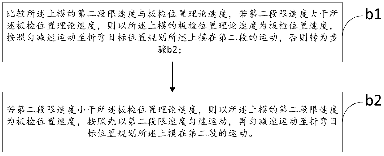
[0070] As mentioned above, the speed planning method of the bending machine, the difference of this embodiment is that, as figure 2 As shown in the flow chart of step b in the bending machine speed planning method of the present invention, said step b includes:
[0071] Step b1, comparing the second speed limit of the upper mold with the theoretical speed of the board inspection position, if the second speed limit is greater than the theoretical speed of the board inspection position, then use the theoretical speed of the board inspection position of the upper die as the board Check the position and speed, and plan the movement of the upper mold in the second section according to the uniform deceleration movement to the bending target position, otherwise go to step b2;
[0072] The calculation formula of uniform motion motion time is:
[0073]
[0074] In the formula, t 2 is the motion time of acceleration motion; a 2 It is the maximum acceleration received by the first...
Embodiment 2
[0082] As mentioned above, the speed planning method of the bending machine, the difference of this embodiment is that in the step b, the calculation formula of the board inspection position speed is:
[0083]
[0084] In the formula, v 1 is the board inspection position speed of the upper die; v 11 is the theoretical velocity of the plate inspection position of the upper die; v L2 It is the speed limit of the second section of the upper die, which is jointly determined by the mechanical properties of the upper die and the bending machine, and the speed limit for moving the board inspection position to the bending target position of the same bending machine is the same.
[0085] The above idea is: the ratio of the difference between the minuend and the subtrahend to the absolute value is a positive or negative number, the positive or negative number is added by one and then divided by two as the coefficient of the subtrahend, then the subtrahend with a positive difference ...
Embodiment 3
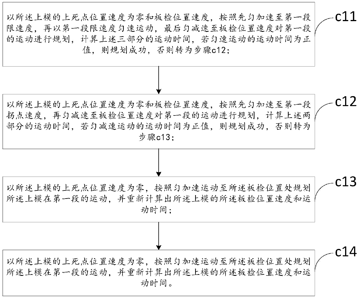
[0088] As mentioned above, the speed planning method of the bending machine, the difference of this embodiment is that, as image 3 The process flow of step c in the bending machine speed planning method of the present invention Figure 1 As shown, the step c includes:
[0089] Step c11, with the speed at the upper dead center position of the upper die being zero and the speed at the board inspection position, first uniformly accelerate to the first speed limit, then move at a uniform speed at the first speed limit, and finally decelerate uniformly to the board inspection position Speed plans the movement of the first segment, and calculates the movement time of the above three parts. If the movement time of the uniform movement is positive, the planning is successful, otherwise go to step c12;
[0090] The calculation formula of the uniform motion time is:
[0091]
[0092] In the formula, t 12 is the motion time of uniform motion; a 1 is the maximum acceleration rec...
PUM
 Abstract
Description
Claims
Application Information
 - R&D
- Intellectual Property
- Life Sciences
- Materials
- Tech Scout
- Unparalleled Data Quality
- Higher Quality Content
- 60% Fewer Hallucinations
Browse by: Latest US Patents, China's latest patents, Technical Efficacy Thesaurus, Application Domain, Technology Topic, Popular Technical Reports.
© 2025 PatSnap. All rights reserved.Legal|Privacy policy|Modern Slavery Act Transparency Statement|Sitemap|About US| Contact US: help@patsnap.com


