
Improved seal for side walls of electrostatic chuck

A technology of electrostatic adsorption and sealing parts, which is applied to the sealing of engines, electrical components, circuits, etc., can solve problems such as uneven distribution of tensile stress, uneven product qualification rate, failure of O-ring 140, etc., and achieve stable product qualification rate , Etching process safety, and the effect of preventing leakage

Active Publication Date: 2016-08-24
MFC SEALING TECH
View PDF4 Cites 3 Cited by
  • Summary
  • Abstract
  • Description
  • Claims
  • Application Information

AI Technical Summary

Problems solved by technology

However, the existing design of the O-ring 140 only includes a sealing point 150 relative to the groove 113, but since the groove 113 is actually very small in size, the O-ring 140 should be evenly nested. It is not easy to enter the groove 113. If the installation is not correct, the internal tensile stress of the O-ring 140 will be unevenly distributed, and the O-ring 140 will be eroded by the plasma gas 120, and longitudinal cracks will occur in the tensile stress area or due to Thinned and damaged to cause air leakage, resulting in failure of the O-ring 140, which will make it difficult to estimate the effective life of the O-ring 140, so that the staff cannot replace the new O-ring 140 in time before it is damaged
Therefore, in the prior art, there are still many problems in the process of plasma etching, such as equipment damage, environmental pollution, and product qualification rate due to the leakage of the working fluid and the erosion of the plasma gas 120 on the groove 113.

Method used


Image

  • Improved seal for side walls of electrostatic chuck
  • Improved seal for side walls of electrostatic chuck
  • Improved seal for side walls of electrostatic chuck

Examples


Embodiment Construction

[0052] In the following, please cooperate with the accompanying drawings and preferred embodiments of the present invention to further elaborate the technical means adopted by the present invention to achieve the intended purpose of the invention.

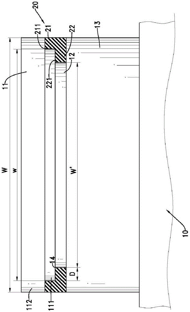
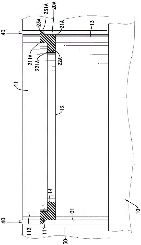
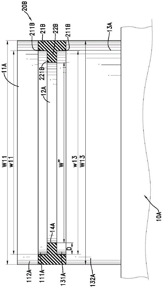
[0053] The improved seal for the side wall of the electrostatic adsorption chuck of the present invention is used on the side wall of the electrostatic adsorption chuck 10, wherein the electrostatic adsorption chuck 10 includes an upper member 11, a bonding layer 12 and a lower member 13, the upper The cross-sectional width w of the bottom 111 of the element 11 is smaller than the cross-sectional width W of the top 112, and the connecting layer 12 connects the bottom 111 of the upper element 11 and the lower element 13, and a groove 14 is formed on the side outer edge of the connecting layer 12, so The groove 14 is formed between the upper element 11 and the lower element 13 .

[0054] Before the improved seal of the side wall of t...


PUM


Abstract

Provided is an improved seal for side walls of electrostatic chuck which enables multiple portions to form between the improved seal and the electrostatic chuck through utilization of arrangement of a plurality of sealing portions. The groove of the electrostatic chuck may be completely filled by the improved seal. Even one of the multiple sealing portions is destroyed in the plasma etching process by the plasma gas, the seal still prevents leaking of the electrostatic chuck effectively. The seal provides a buffer period for engineers to replace the improved seal before the leaking occurs. Danger of leaking caused by abrupt breaking of the barrier seal is reduced. Furthermore, the seal facilitates stability and safety of the plasma etching process. The yield of products manufactured by the electrostatic chuck may be improved.

Description

technical field [0001] The invention is an improved seal for the side wall of the electrostatic adsorption support plate of plasma etching equipment, especially a seal that can be filled into the groove of the electrostatic adsorption support plate and can have multiple sealing points between the groove and the groove. Improved seals. Background technique [0002] Prior art plasma etching equipment such as Figure 9 As shown, it includes an electrostatic adsorption chuck 90, which includes an upper element 91 made of ceramic dielectric material, a lower element 92, and a bonding layer 93 made of soft material , the connection layer 93 connects the upper element 91 and the lower element 92, and the periphery of the electrostatic adsorption chuck 90 is further provided with an extension unit 100 for extending and carrying wafers, and there is a gap between the electrostatic adsorption chuck 90 and the extension unit 100 110 and groove 113, the gap 110 allows the process plasm...

Claims


Application Information

Patent Timeline
Patent Type & Authority Applications(China)
IPC IPC(8): H01L21/683H01J37/20
CPCH01J37/20H01L21/6833H01J2237/20H01J37/32715H01J37/3288H01J37/32697H01J37/32513F16J15/106
Inventor 张佑语黄俊尧
Owner MFC SEALING TECH
Learn More