
Zero-crossing trigger control circuit for anti-parallel thyristor split-phase switched capacitor

A zero-crossing trigger and control circuit technology, applied in reactive power compensation, reactive power adjustment/elimination/compensation, etc., can solve the problems of non-zero-crossing triggering of thyristors, unreasonable trigger pulses, damage to thyristor modules, etc., and achieve stable operation Reliable, avoid overvoltage breakdown of isolation devices, and improve reliability

Active Publication Date: 2016-08-24
LANGFANG IN POWER ELECTRIC
View PDF8 Cites 2 Cited by
  • Summary
  • Abstract
  • Description
  • Claims
  • Application Information

AI Technical Summary

Problems solved by technology

The core of the thyristor switching capacitor equipment is the thyristor zero-crossing trigger control circuit, and if the zero-crossing signal acquisition is inaccurate and the trigger timing is unreasonable, it will cause the thyristor to trigger non-zero-crossing, which will cause inrush current impact on the power grid, or the trigger pulse is unreasonable , the secondary surge will damage the thyristor module

Method used


Image

  • Zero-crossing trigger control circuit for anti-parallel thyristor split-phase switched capacitor
  • Zero-crossing trigger control circuit for anti-parallel thyristor split-phase switched capacitor
  • Zero-crossing trigger control circuit for anti-parallel thyristor split-phase switched capacitor

Examples


Embodiment Construction

[0056] The present invention will be further described in detail below in conjunction with the accompanying drawings and specific embodiments.

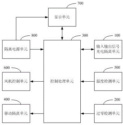
[0057] see figure 1 , in one embodiment, the zero-crossing trigger control circuit of the anti-parallel thyristor split-phase switching capacitor may include: an input and output signal photoelectric isolation unit 100 , a control processing unit 300 , a zero-crossing detection unit 200 and a drive isolation unit 400 . Wherein, the control processing unit 300 is respectively connected with the input and output signal photoelectric isolation unit 100 , the zero-crossing detection unit 200 and the driving isolation unit 400 . The input and output signal photoelectric isolation unit 100 is configured to generate a low-level control signal according to an external control signal and send it to the control processing unit 300 . The zero-crossing detection unit 200 is used to detect whether the voltages at both ends of the thyristor are eq...


PUM


Abstract

The invention discloses a zero-crossing trigger control circuit for an anti-parallel thyristor split-phase switched capacitor. The zero-crossing trigger control circuit comprises an input / output signal photoelectric isolation unit, a control processing unit, a zero-crossing detection unit and a drive isolation unit; the input / output signal photoelectric isolation unit generates a low-level control signal according to an external control signal, and sends the low-level control signal to the control processing unit; the zero-crossing detection unit detects voltages at two ends of a thyristor, and sends the voltages to the control processing unit; when the voltages at the two ends of the thyristor are equal, the control processing unit generates a drive signal for controlling starting of the thyristor according to the low-level control signal, and sends the drive signal to the drive isolation unit; when the voltages at the two ends of the thyristor are unequal, the control processing unit generates a stop signal for controlling turn-off of the thyristor, and sends the stop signal to the drive isolation unit; and the drive isolation unit drives zero-crossing triggering of the thyristor according to the drive signal, and stops driving the zero-crossing triggering of the thyristor according to the stop signal. The zero-crossing trigger control circuit can prevent non-zero-crossing triggering of the thyristor.

Description

technical field [0001] The invention relates to the technical field of reactive power compensation and power quality control, in particular to a zero-crossing trigger control circuit of an anti-parallel thyristor split-phase switching capacitor. Background technique [0002] With the development of social economy and technological progress, the application of a large number of high-power power electronic equipment has caused the lack of large-capacity reactive power in the grid, low power factor, increased voltage and current harmonic content, and unbalanced three-phase voltage, etc., and the power quality has deteriorated. serious. However, the traditional contactor switching capacitor reactive power compensation equipment has been unable to meet the requirements of rapidity, accuracy, economy and reliability of reactive power compensation in the field of low-voltage and high-power reactive power compensation. Therefore, as a more optimized solution, thyristor switched cap...

Claims


Application Information

Patent Timeline
IPC IPC(8): H02J3/18
CPCH02J3/18Y02E40/30
Inventor 杨倩倩高学超孙大伟何永超邢勇张洪涛
Owner LANGFANG IN POWER ELECTRIC
Learn More