Permanent magnet, rotor, motor and compressor

A technology of permanent magnets and rotors, applied in the direction of magnetic circuit rotating parts, magnetic circuits, electrical components, etc., can solve the problems of poor manufacturability and poor mechanical strength characteristics of permanent magnets, achieve excellent manufacturability, and improve magnetic flux utilization. , cost-effective effect

Active Publication Date: 2016-08-24
GUANGDONG MEIZHI COMPRESSOR +1
View PDF7 Cites 3 Cited by
  • Summary
  • Abstract
  • Description
  • Claims
  • Application Information

AI Technical Summary

Problems solved by technology

When the special-shaped structure is improperly set, it will lead to poor mechanical strength characteristics of the permanent magnet, and poor manufacturability

Method used


Image

  • Permanent magnet, rotor, motor and compressor
  • Permanent magnet, rotor, motor and compressor
  • Permanent magnet, rotor, motor and compressor

Examples


Embodiment 1

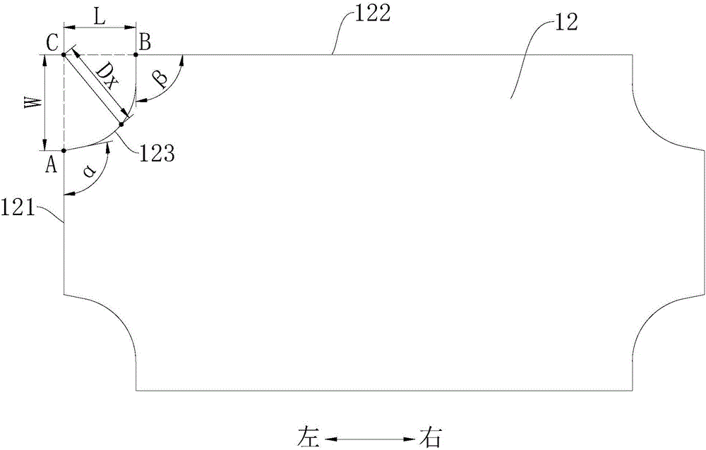
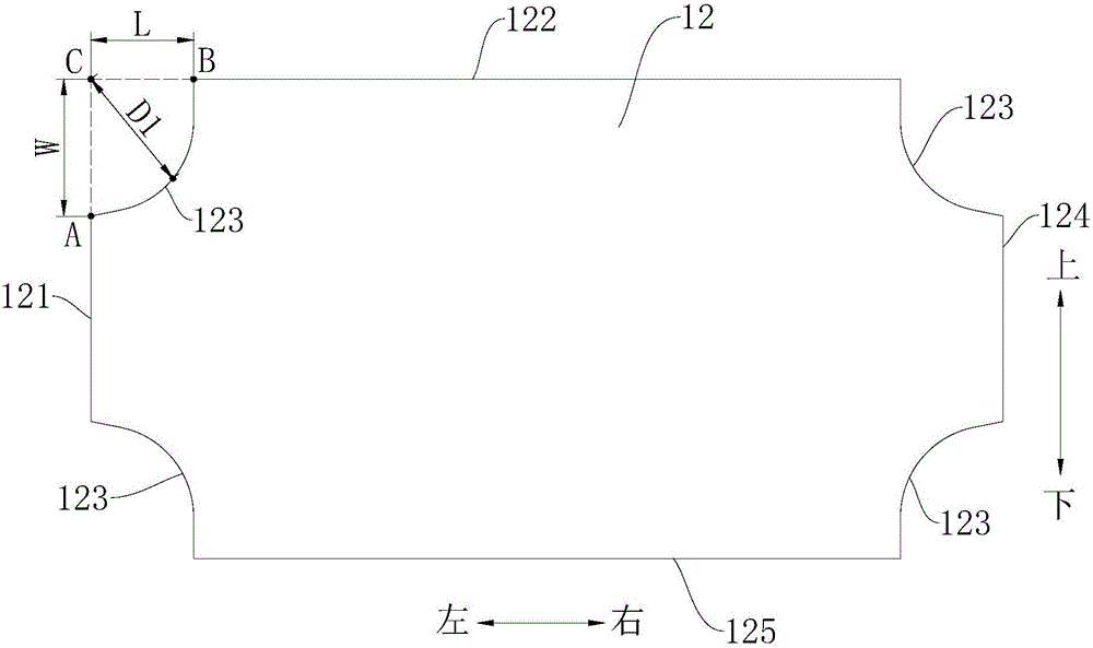
[0089] Such as figure 2 and image 3 As shown, the working surface of the permanent magnet 12 is surrounded by a first side 121, a second side 122, a third side 124 and a fourth side 125 which are connected end to end in order to form a substantially rectangular shape, and the first side between a group of adjacent sides Both the end points and the tail end points are connected by a transition edge 123 . The working face of permanent magnet 12 is about the lengthwise direction of permanent magnet 12 (for example figure 2 The centerline of the left and right directions shown in ) is symmetrical, and the working surface of the permanent magnet 12 is about the width direction of the permanent magnet 12 (for example figure 2 Centerline symmetry in the up and down directions shown in ). The transitional side 123 connected between the first end point A of the first side 121 and the tail end point B of the second side 122 will be described below.

[0090] Specifically, such as...

Embodiment 2

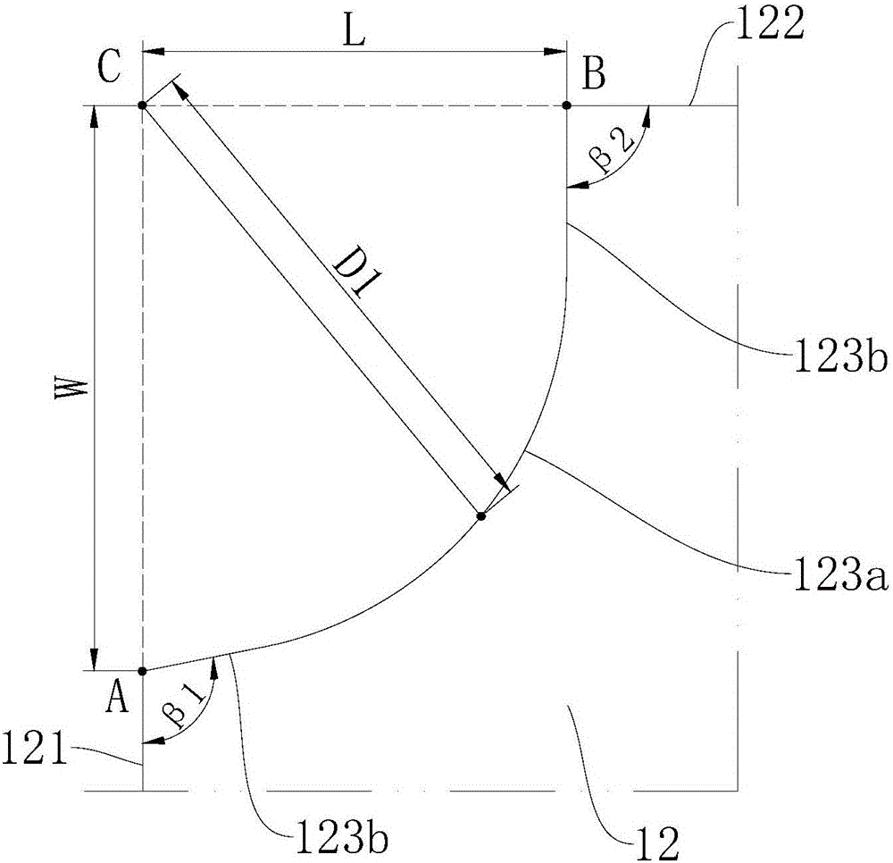
[0099] Such as Figure 4 and Figure 5 As shown, the structure of this embodiment is roughly the same as that of Embodiment 1, the only difference is that: the transition edge 123 in Embodiment 1 only includes a sub-arc segment 123a, while the transition edge 123 in Embodiment 2 Contains two sub-arc segments 123a.

[0100] Assuming that the distance between the midpoint of one of the sub-arc segments 123a and the intersection point C in the transition side 123 in the present embodiment is D1, the distance between the midpoint of the other sub-arc segment 123a and the intersection point C is D2, and D1 and D2 satisfies:

[0101] W L / W 2 + L 2 ≤ D 1 ≤ 0.8 W 2 + L ...

Embodiment 3

[0105] Such as Figure 6 and Figure 7 As shown, the structure of this embodiment is substantially the same as that of Embodiment 1, wherein the same components use the same reference numerals, the only difference is that the transition edge 123 in Embodiment 1 only includes one sub-arc segment 123a, In this embodiment, however, the transition edge 123 includes three sub-arc segments 123a.

[0106] Let the distance between the midpoint of the first sub-arc section 123a and the intersection point C along the direction from bottom to top in the transition side 123 in the present embodiment be D1, the midpoint of the second sub-arc section 123a and the intersection point C The distance is D2, the distance between the midpoint of the third sub-arc segment 123a and the intersection point C is D3, and D1, D2 and D3 satisfy:

[0107] W L / W 2 + L ...


PUM


Abstract

The invention discloses a permanent magnet, a rotor, a motor and a compressor. The working surface of the permanent magnet comprises first edges and second edges which are arranged perpendicularly; the first end point of each first edge and the tail end point of each second edge are connected through a transitional edge; the corresponding transitional edge is positioned on one side, close to the center of the working surface, of the connecting line of the corresponding first end point and the corresponding tail end point; and each transitional edge comprises at least one sub circular arc section, or a combination of at least one sub circular arc section and at least one sub straight line section. According to the permanent magnet provided by the invention, by limiting the shape of the transitional edges, the material cost can be lowered, the mechanical strength of the permanent magnet can be enhanced, and the manufacturing percent of pass of the permanent magnet can be improved.

Description

technical field [0001] The invention relates to the technical field of refrigeration equipment, in particular to a permanent magnet, a rotor, a motor and a compressor. Background technique [0002] The working surface of the rare earth embedded permanent magnet is generally a square structure, that is, the long side and the short side of the working surface are directly connected. The magnetic flux utilization rate of this structure is low, and the cost of the permanent magnet is high, so the cost performance of the permanent magnet motor is low. [0003] In the related art, in order to reduce the cost of the permanent magnet and improve the utilization rate of the sting, the working surface of the permanent magnet can be arranged in a special-shaped structure. However, when the special-shaped structure is improperly arranged, it will result in poor mechanical strength characteristics of the permanent magnet and poor manufacturability. Contents of the invention [0004] ...

Claims


Application Information

Patent Timeline
IPC IPC(8): H02K1/06H02K1/27
CPCH02K1/06H02K1/2706H02K2213/03
Inventor 乔正忠毛临书于明湖
Owner GUANGDONG MEIZHI COMPRESSOR
Why Eureka
Try Eureka