
Three-level optimization PWM method based on PSO algorithm
A three-level, algorithmic technology, applied in the direction of pulse duration/width modulation, etc., can solve the problem of general harmonic optimization effect, and achieve good harmonic optimization effect and good sine degree effect
- Summary
- Abstract
- Description
- Claims
- Application Information
AI Technical Summary
Problems solved by technology
Method used
Image

Examples
Embodiment Construction
[0022] The preferred implementation of the PSO algorithm-based three-level optimized PWM method of the present invention will be described in detail below in conjunction with the accompanying drawings.
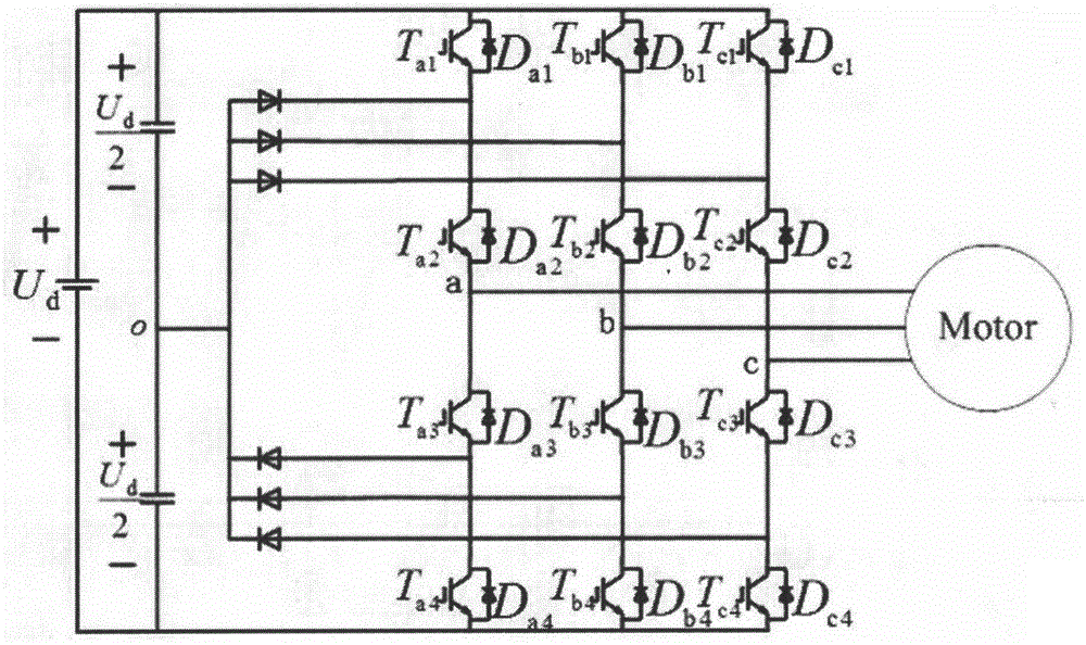
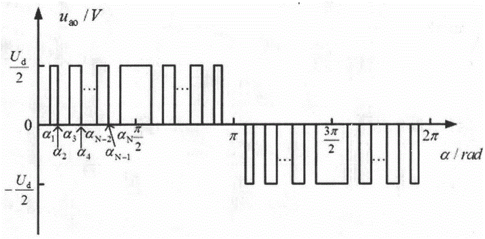
[0023] figure 1 and figure 2 Show the specific implementation of the three-level optimized PWM method based on the PSO algorithm of the present invention: figure 1 The main circuit structure diagram of the three-level traction inverter-motor drive system is given. assumed figure 1 The output phase voltage of the three-level inverter is symmetric in a quarter cycle and anti-symmetric in a half cycle, such as figure 2 shown. It can be seen from the Fourier transform that such a waveform can ensure that the output voltage of the inverter does not contain DC components and even harmonic components. It can be seen from the symmetry of the waveform that as long as the N pulse switching angles in the first quarter cycle are determined, the output voltage pulse sequence of the ...
PUM
 Abstract
Description
Claims
Application Information