
Compensation method for installation error of Hall sensor in permanent magnet synchronous motor

A technology of permanent magnet synchronous motor and hall sensor, which is applied in the estimation/correction of motor parameters, electronic commutator, etc., and can solve the initial installation position deviation of permanent magnet synchronous motor and the installation error of hall sensor of permanent magnet synchronous motor and other problems, to achieve the effect of reducing position deviation, good sine degree and improving sine degree

Pending Publication Date: 2022-01-25
JIANGSU UNIV OF SCI & TECH
View PDF0 Cites 0 Cited by
  • Summary
  • Abstract
  • Description
  • Claims
  • Application Information

AI Technical Summary

Problems solved by technology

[0004] The purpose of the present invention is to provide a method for compensating the installation error of the hall sensor of the permanent magnet synchronous motor based on the least square method, so as to solve the situation that the permanent magnet synchronous motor has a deviation in the initial installation position of the hall position sensor in the prior art

Method used


Image

  • Compensation method for installation error of Hall sensor in permanent magnet synchronous motor
  • Compensation method for installation error of Hall sensor in permanent magnet synchronous motor
  • Compensation method for installation error of Hall sensor in permanent magnet synchronous motor

Examples


Embodiment Construction

[0035] The technical solution of the present invention will be further described in detail below in conjunction with the accompanying drawings.

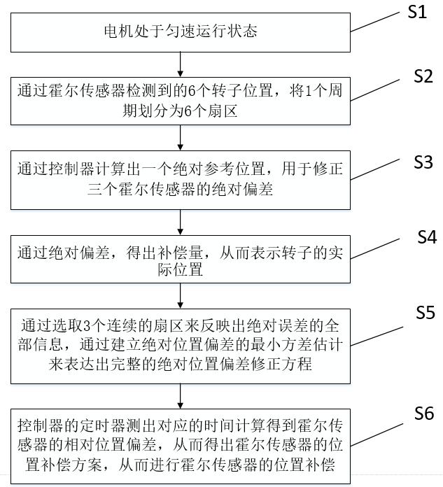
[0036] The invention provides a method for compensating the installation error of the hall sensor of the permanent magnet synchronous motor based on the least square method, such as figure 1 As shown, the specific method includes the following steps:

[0037] Step S1: The permanent magnet synchronous motor first adopts a constant voltage ratio control method to make the motor run at a constant speed.

[0038] Step S2: Divide one period into six sectors through the six rotor positions detected by the Hall sensor.

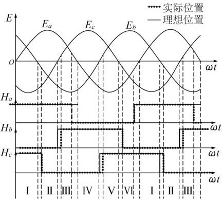
[0039] Such as figure 2 As shown, when the motor is running at a constant speed, a period is divided into 6 sectors through the 6 rotor positions detected by the Hall sensor, and the controller can detect the electrical angle corresponding to each sector. The specific calculation formula for:

[0040]

[0041] Among...


PUM


Abstract

The invention discloses a compensation method for the installation error of a Hall sensor in a permanent magnet synchronous motor. The method comprises the following steps: firstly, enabling the motor to be in a constant-speed operation state by adopting a constant-voltage frequency ratio control mode; then, dividing one period into six sectors according to six rotor positions detected by Hall sensors; calculating an absolute reference position through a controller, which is used for correcting the absolute deviation of the three Hall sensors; finding the compensation amount through the obtained absolute deviation, so that the actual position of the rotor is expressed; reflecting all information of the absolute error by selecting three continuous sectors, and expressing a complete absolute position deviation correction equation by establishing minimum variance estimation; and performing calculation according to the corresponding time detected by a timer of the controller to obtain a relative position deviation, and performing position compensation. Through the method, the harmonic content of the current can be reduced, the sine degree is better, the actual position of the rotor can be accurately obtained, and meanwhile the sine degree of the current can be improved.

Description

technical field [0001] The invention relates to the technical field of permanent magnet synchronous motors, in particular to a compensation method for installation errors of Hall sensors in permanent magnet synchronous motors. Background technique [0002] The permanent magnet synchronous motor control system has broadened many fields, and now it can realize motion control with high precision, fast response, high stability and high efficiency and energy saving. Hall sensors are divided into linear Hall sensors and are divided into linear Hall sensors and switch Hall sensors. The linear Hall sensor is composed of a Hall element, a linear amplifier and an emitter follower, and it outputs an analog value. The switch-type Hall sensor is composed of a voltage regulator, a Hall element, a differential amplifier, a Schmitt trigger and an output stage, which outputs digital quantities. [0003] When there is a deviation in the position of the Hall sensor in the permanent magnet sy...

Claims


Application Information

Patent Timeline
IPC IPC(8): H02P6/16H02P23/14
CPCH02P6/16H02P23/14
Inventor 张懿徐斌魏海峰陈椒娇
Owner JIANGSU UNIV OF SCI & TECH
Learn More