
Sensor intelligent manufacturing calibration device and calibration method thereof

A technology for intelligent manufacturing and calibration devices, which is applied in branch office equipment, electrical components, telephone communications, etc., can solve the problems of poor versatility, poor consistency, and low calibration accuracy of the automatic calibration system, so as to improve test consistency and accuracy, Increased versatility and consistent light intensity

Active Publication Date: 2018-11-09
QINGDAO HISENSE MOBILE COMM TECH CO LTD
View PDF5 Cites 0 Cited by
  • Summary
  • Abstract
  • Description
  • Claims
  • Application Information

AI Technical Summary

Problems solved by technology

However, after the area of ​​the leakage hole becomes smaller, affected by factors such as assembly errors, different light sensors and distance sensors transmit light to the outside, and the magnitude of the distance sensing value will be different, and the consistency is very poor, which seriously affects users. Experience
Chinese patent application number 201310714192.8 discloses a distance sensor automatic calibration system and method for a mobile terminal product production line. The automatic calibration of the distance sensor is realized by installing some fluorescent lamps and baffles on the production line. However, due to the consistent light intensity of the fluorescent lamps Poor performance, different sunlight intensity is not the same, coupled with the influence of the ambient light on site, the sensor calibration values ​​on different portable mobile terminals will be different, and this method is not suitable for light sensors, and additional equipment is required to The optical sensor is calibrated, resulting in poor versatility and low calibration accuracy of the automatic calibration system in the prior art

Method used


Image

  • Sensor intelligent manufacturing calibration device and calibration method thereof
  • Sensor intelligent manufacturing calibration device and calibration method thereof
  • Sensor intelligent manufacturing calibration device and calibration method thereof

Examples


Embodiment Construction

[0021] In order to make the purpose, technical solutions and advantages of the embodiments of the present invention clearer, the technical solutions in the embodiments of the present invention will be clearly and completely described below in conjunction with the drawings in the embodiments of the present invention. Obviously, the described embodiments It is a part of embodiments of the present invention, but not all embodiments. Based on the embodiments of the present invention, all other embodiments obtained by persons of ordinary skill in the art without creative efforts fall within the protection scope of the present invention.

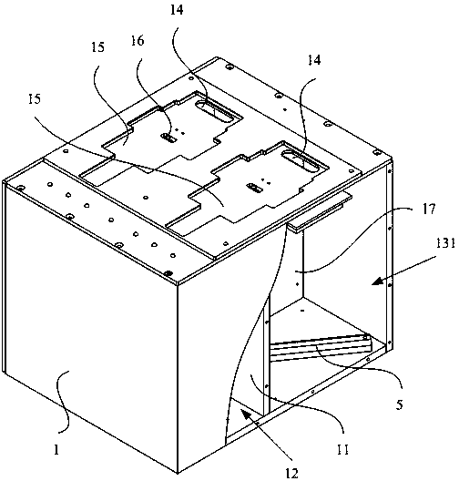
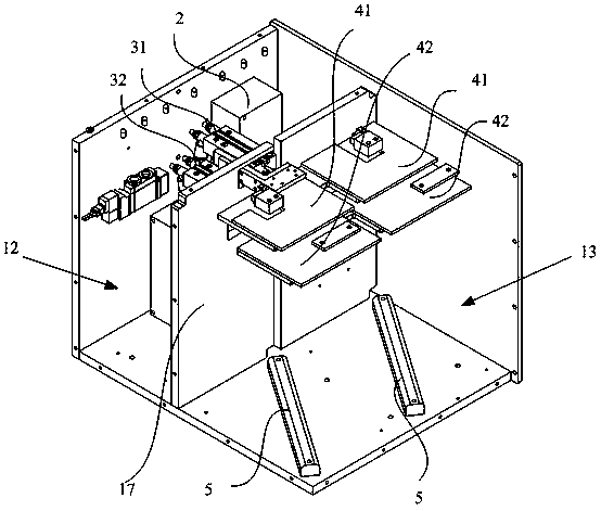
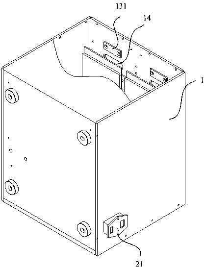
[0022] Such as Figure 1-Figure 3 As shown, the sensor intelligent manufacturing calibration device of this embodiment includes a casing 1, a control board 2, a cylinder assembly, a gray board assembly and a light source 5; a partition 11 is arranged in the casing 1, and the partition 11 connects the casing The interior is divided into an install...


PUM


Abstract

The invention provides an intelligent manufacturing calibrating device for a sensor, and a calibrating method thereof. The intelligent manufacturing calibrating device for a sensor includes a housing, a control panel, a cylinder assembly, a gray plate assembly and a light source, wherein a separator plate is arranged in the housing, and separates the internal of the housing into an installation room and a detection darkroom; the cylinder assembly includes a first cylinder and a second cylinder which are fixed in the installation room; the gray plate assembly includes a first gray plate and a second gray plate which are arranged in the detection darkroom; the first gray plate is connected with a piston rod of the first cylinder; the second gray plate is connected with a piston rod of the second cylinder; the first gray plate is arranged above the second gray plate; the top of the housing is also provided with a test through hole which communicates with the detection darkroom; the light source is arranged in the detection darkroom; a solenoid valve of the first cylinder and a solenoid valve of the second cylinder are connected with the control panel; the light source is also connected with the control panel; and the top wall of the detection darkroom is also provided with a calibration optical sensor. Therefore, the universality and the calibrating accuracy of the intelligent manufacturing calibrating device for a sensor can be improved.

Description

technical field [0001] The invention relates to the technical field of intelligent manufacturing, in particular to a sensor intelligent manufacturing calibration device and a calibration method thereof. Background technique [0002] Currently, portable mobile terminals (such as mobile phones and handheld computers) are widely used by users because of their portability. Portable mobile terminals are usually equipped with light sensors and distance sensors. Affected by the appearance design of portable mobile terminals, for the leak holes of light sensors and distance sensors arranged on the front of portable mobile terminals (corresponding to light sensors and distance sensors on the outer surface of portable mobile terminals) The through hole opened by the sensor is used to sense the external light intensity and the distance of the occluder) The size of the hole needs to be designed to be smaller to meet the requirements of appearance and user satisfaction. However, after t...

Claims


Application Information

Patent Timeline
Patent Type & Authority Patents(China)
IPC IPC(8): H04M1/24
CPCH04M1/24
Inventor 林文王旭明赵先升刘赛范炜东
Owner QINGDAO HISENSE MOBILE COMM TECH CO LTD
Learn More