Implantable urinary continence device

A urine device and implantable technology, applied in the field of medical devices, can solve problems such as difficulty in installation and urine control effects, drastic changes in shape, poor blood supply to the penis, etc., and achieve simple structure, small trauma, and daily Ease of use

Inactive Publication Date: 2016-08-31
张秀军
View PDF13 Cites 2 Cited by
  • Summary
  • Abstract
  • Description
  • Claims
  • Application Information

AI Technical Summary

Problems solved by technology

However, these solutions are easy to cause discomfort to the human body when clamped on the penis body. Long-term use will lead to poor blood supply to the penis. The most critical problem is that the shape of the male penis changes drastically at different t

Method used


Image

  • Implantable urinary continence device
  • Implantable urinary continence device
  • Implantable urinary continence device

Examples


Embodiment 1

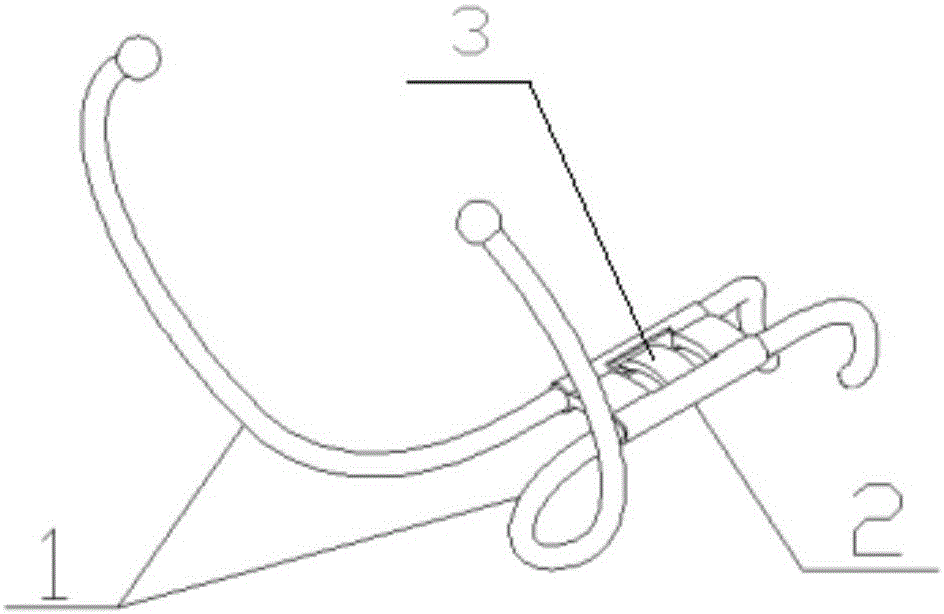
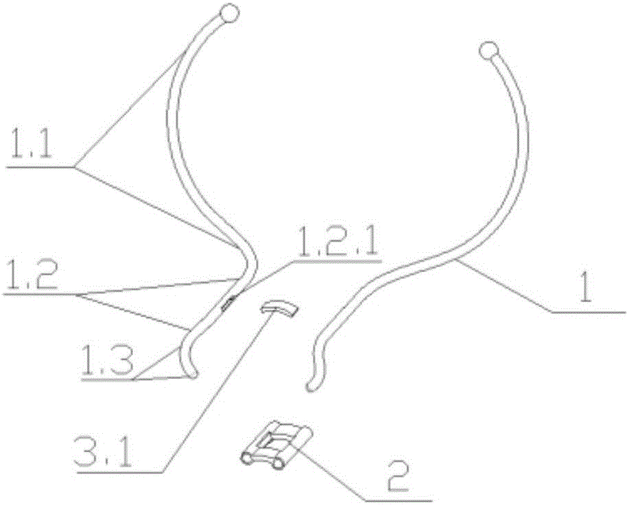
[0068] Such as Figure 1 to Figure 3 The implanted urination control device shown is composed of two device handles 1, a fixed block 2 and a device handle rotation angle limiting mechanism 3, and the two device handles 1 are respectively the first device handle and the second device handle. The instrument handle 1 is composed of a handle plectrum 1.1, a connecting shaft 1.2 and a urethral plectrum 1.3. One end of the connecting shaft 1.2 bends upwards to extend the handle plectrum 1.1, and the other end bends downwards to extend the urethral plectrum 1.3. The first instrument handle and the second instrument handle are mirror-symmetrically arranged, especially the part of the handle pick 1.1 and the connecting shaft 1.2 is symmetrical with respect to the central axis, the handle pick 1.1 is an arc-shaped structure extending to the side, and the terminal is inward Bending, the angle between the plane formed by the two handle picks 1.1 and the plane formed by the two connecting ...

Embodiment 2

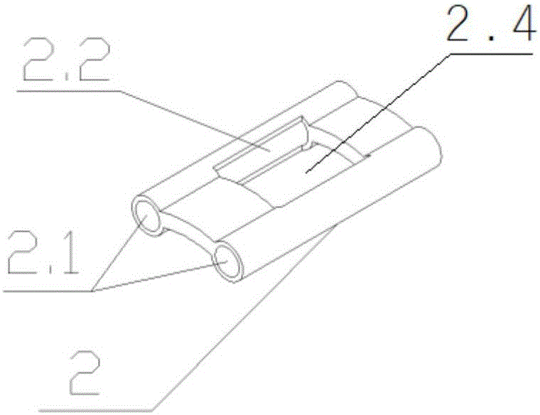
[0071] Such as Figure 4 to Figure 8 The implanted urination control device shown is the same as that in Embodiment 1. The first device handle and the second device handle are arranged mirror-symmetrically, especially the parts of the handle paddle 1.1 and the connecting shaft 1.2 are symmetrical with respect to the central plane, and the handle The paddle 1.1 is an arc-shaped structure extending to the side, and the terminal is bent inward. The angle between the plane formed by the two handle paddles 1.1 and the plane formed by the two connecting shafts 1.2 is an obtuse angle of 110°. Moving the handle plectrum 1.1 can make the connecting shaft 1.2 rotate inwardly. The connecting shafts 1.2 of the two instrument handles 1 are sleeved in the communication hole 2.1 inside the fixed block 2 in parallel. The urethral plectrum 1.3 of the instrument handle 1 is an arc-shaped structure that bends to the side of the opposite side. The two urethral plectrums 1.3 are arranged in a fro...

Embodiment 3

[0073] Such as Figure 9 to Figure 11In the implanted urination control device shown, the rest of the first device handle and the second device handle are arranged mirror-symmetrically with the embodiment 2, especially the part of the handle dial 1.1 and the connecting shaft 1.2 is symmetrical with respect to the central axis, and the handle dial The piece 1.1 is an arc-shaped structure extending to the side, and the terminal is bent inward. The angle between the plane formed by the two handle paddles 1.1 and the plane formed by the two connecting shafts 1.2 is 120° obtuse angle, and it is moved inward. The handle pick 1.1 can make the connecting shaft 1.2 turn inward. The connecting shafts 1.2 of the two instrument handles 1 are sleeved in the communication hole 2.1 inside the fixed block 2 in parallel. The urethral plectrum 1.3 of the instrument handle 1 is also an arc-shaped structure bent sideways, and its terminal end is bent inward for clamping, but the urethral plectru...


PUM


Abstract

The invention relates to an implantable urinary continence device which comprises two device handles. Each device handle comprises a connecting shaft, a urethra shifting piece and a handle shifting piece. The two device handles are movably connected through the connecting shafts. The two handle shifting pieces move relatively to control the first urethra shifting piece to do opening motion relative to the urethra shifting piece of the second device handle. The urethra shifting piece of one device handle is located in front of the urethra shifting piece of the other device handle. The implantable urinary continence device further comprises a device handle rotating angle limiting mechanism for limiting the opening angles of the urethra shifting pieces. The implantable urinary continence device has the advantages that the structure is simple and stable, few traumas is caused by the implanting way, the urinary continence effect is ideal, the uracratia problem is well solved, no trace is formed on the body surface, daily use is convenient, and life-long free maintenance is achieved.

Description

technical field [0001] The invention relates to the technical field of medical devices, in particular to an implanted urination controller which is implanted in the penis to realize autonomous control of urination. Background technique [0002] Urinary leakage or even urinary incontinence caused by trauma, neurological abnormalities, surgical complications and aging is an important reason for the quality of life of patients with severe imaging and even some diseases such as urinary tract infections. In response to this problem, At present, people have developed a variety of technologies to solve this problem, and the main solutions are divided into two categories, (1) surgical treatment methods, and (2) non-surgical treatment methods. [0003] Among them, the implantable artificial urethral sphincter technology represented by EP2810616A1 and US20080146868A1 is the surgical treatment method. This type of technology usually consists of a urethral restraint device, a switch dev...

Claims


Application Information

Patent Timeline
IPC IPC(8): A61F2/00
CPCA61F2/0054A61F2/0036A61F2/0018A61F2/0004A61F2210/009A61F2220/0091A61B2090/035A61B17/122A61B2017/00367A61B2017/00862A61F2/00
Inventor 孙颖浩
Owner 张秀军
Why Eureka
Try Eureka