Peristaltic pump with variable angle pressure rollers

A peristaltic pump and pressure technology, applied in the field of transmission, can solve the problem of undesired pulsation on the high-pressure side, and achieve the effect of minimizing pulsation and preventing pulsation

Active Publication Date: 2016-08-31
B BRAUN AVITUM
View PDF4 Cites 3 Cited by
  • Summary
  • Abstract
  • Description
  • Claims
  • Application Information

AI Technical Summary

Problems solved by technology

[0003] A disadvantage that unfortunately often occurs with known dialysis machines and methods is that, during the pumping operation of the delivered fluid volume, undesired pulsations may occur on the high pressure side
[0004] Another deleterious effect in the known method and in the dialysis machine consists in the fact that in the case of the delivery of blood as fluid, during the previously described pressure compensation, the blood is squeezed through the gap between the delivery volume section and the high-pressure side. open the bottleneck

Method used


Image

  • Peristaltic pump with variable angle pressure rollers
  • Peristaltic pump with variable angle pressure rollers
  • Peristaltic pump with variable angle pressure rollers

Examples


Embodiment Construction

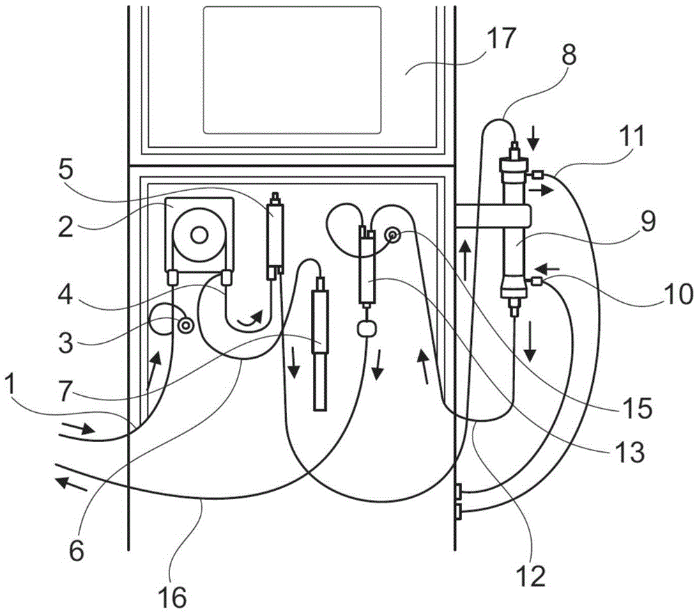
[0035] figure 1 A cutout of a device for extracorporeal blood therapy according to the invention is exemplified. Here, essentially the entire extracorporeal blood route of the device is shown. The overall extracorporeal blood line comprises an arterial blood line 1 by means of which blood is led from a patient (not shown) to a peristaltic pump 2 of a treatment device. Upstream of the peristaltic pump 2 , an arterial pressure sensor 3 is provided, through which the pressure upstream of the peristaltic pump 2 , ie the low pressure side pressure, is measured. On the high-pressure side of the peristaltic pump 2 , a high-pressure blood line 4 leads to an arterial air trap 5 . Directly at the outlet of the peristaltic pump 2 , additives can be added to the blood provided in the system by means of the feed line 6 and the pump 7 , eg heparin for blood thinning.

[0036] From the arterial air trap 5 a line 8 leads blood under high pressure but not supplied to the dialyzer 9 . On th...


PUM


Abstract

A method of conveying fluid in an apparatus for extracorporeal blood treatment is disclosed, wherein fluid is conveyed by a peristaltic pump from a low-pressure side to a high-pressure side, an elastically deformable fluid line arranged between the low-pressure side and the high-pressure side being deformed between a support surface and a rotor rotating with respect to the latter and having at least two pinch elements, wherein the pinch elements are repositioned at angles relative to each other during rotation of the rotor for causing pre-compression. A dialysis machine including a peristaltic pump conveying fluid from a low-pressure side to a high-pressure side, wherein the peristaltic pump is arranged to receive an elastically deformable fluid line between the low-pressure side and the high-pressure side and includes a support surface supporting the fluid line and a rotor is also disclosed, the rotor including at least two pinch elements each deforming the fluid line between itself and the support surface, wherein the pinch elements are formed to be repositioned at angles relative to each other in the direction of rotation.

Description

technical field [0001] The invention relates to a method for conveying fluid, in particular blood, in a device for extracorporeal blood therapy, in particular in a dialysis machine, wherein the fluid is conveyed from a low-pressure side to a high-pressure side by means of a peristaltic pump and is arranged between the low-pressure side and the high-pressure side The elastically deformable fluid line between the high-pressure side deforms, in particular presses, between the support surface and the rotor, which rotates face-to-face with the support surface and has at least two contact pressing elements. Furthermore, the invention relates to a dialysis machine comprising a peristaltic pump conveying fluid from a low-pressure side to a high-pressure side, said peristaltic pump comprising an elastically deformable fluid line between the low-pressure side and the high-pressure side, a supporting fluid A support surface for the line, and a rotor, wherein the rotor comprises at least ...

Claims


Application Information

Patent Timeline
Patent Type & Authority Applications(China)
IPC IPC(8): A61M1/10A61M1/16F04B49/00
CPCA61M1/16F04B49/00A61M60/113A61M60/279A61M60/441A61M60/531A61M60/554A61M60/37A61M2205/3334A61M1/1603A61M1/267F04B43/1253F04B49/20F04B51/00
Inventor 奥利弗·沙佛卡伊尤韦·里特尔
Owner B BRAUN AVITUM
Why Eureka
Try Eureka